SNiP 3.05.03-85
________________
Registered by Rosstandard as SP 74.13330.2011. -
Note database manufacturer.
BUILDING REGULATIONS
HEATING NETWORK
Date of introduction 1986-07-01
Developed by the Institute of Organizhergostroy Midnergo of the USSR (L. Ya. Mukomel - Head of the topic; Cand. Tech. Sciences S. S. Jacobson).
Made by the USSR Ministry of Energy.
Prepared for the approval of the head of the USSR (N. A. Shishov).
Approved by the Resolution of the USSR State Committee on Construction Affairs of October 31, 1985 N 178.
With the introduction of SNIP on 3.05.03-85 "Heat Networks" loses force SNIP III-30-74 "Water supply, sewage and heat supply. External networks and structures".
Coordinated with Gosgorthnadzor of the USSR on April 15, 1985
These rules apply to the construction of new, expansion and reconstruction of existing thermal networks,
transporting hot water temperature T | 200 hail and pressure | 2.5 MPa (25 kgf / sq. CM) |
from the source of thermal energy to heat consumers (buildings, structures).
1. GENERAL PROVISIONS
1. GENERAL PROVISIONS
1.1. During the construction of new, expanding and reconstruction of existing thermal networks, in addition to the requirements of work drawings, work projects (PPR) and these rules, the requirements should also be observed. Snip 3.01.01-85, SNiP 3.01.03-84, SNIP III-4-80 and standards .
1.2. Work on the manufacture and installation of pipelines, which apply to the requirements of the rules of the device and the safe operation of the pair and hot water pipelines of the USSR State Migorekhnadzor (in the future, the USSR State University Rules) must be carried out in accordance with the specified rules and requirements of these standards and rules.
1.3. Completed thermal networks should be commissioned in accordance with the requirements of SNiP III-3-81.
2. Earthwork
2.1. Earthworks and work on the base device must be carried out in accordance with the requirements of SNIP III-8-76, SNIP 3.02.01-83, CH 536-81 and this section.
2.2. The smallest width of the trench bottom with a volatile tubing of pipes should be equal to the distance between the outer lateral edges of the insulation of the extreme pipelines of thermal networks (associated drainage) with the addition to each side for pipelines with a conditional diameter
the width of the pit in the trench for welding and insulation of the joints of pipes with a volatile laying of pipelines should be taken equal to the distance between the outer lateral glands of insulation of extreme pipelines with the addition of 0.6 m per side, the length of the pitfall is 1.0 m and the depth of the lower edge of the pipeline insulation - 0.7 m, if other requirements are not substantiated by work drawings.
2.3. The smallest width of the trench bottom with a channel laying of heat networks should be equal to the width of the channel, taking into account the formwork (on monolithic areas), waterproofing, associated drainage and water-gravy devices, the constructions of the trench attachment with the addition of 0.2 m. In this case, the trench width must be at least 1 0 m.
If you need to work between the outer edges of the channel design and walls or slopes of the trench, the width between the outer edges of the channel design and walls or slopes of the trench in the light should be at least: 0.70 m - for trenches with vertical walls and 0.30 m - for trenches With slopes.
2.4. The backflow of trenches with a non-channel and channel laying of pipelines should be performed after conducting preliminary tests of pipelines for strength and tightness, full of insulating and construction and installation work.
Reverse backfill must be produced in the specified technological sequence:
skipping sinuses between the pipelines of the infantal gasket and the base;
simultaneous uniform folding of the sinuses between the walls of the trenches and pipelines in the volatile gasket, as well as between the walls of the trench and the channel, the chambers with a channel gasket at a height of at least 0.20 m above the pipelines, channels, cameras;
flipping trenches to design marks.
The backflow of trenches (pita), which are not transmitted to additional external loads (except for their own weight of the soil), as well as tranches (buttels) in the intersection areas with existing underground communications, streets, roads, roads, squares and other facilities and industrial sites It should be performed in accordance with the requirements of SNIP III-8-76.
2.5. After turning off the temporary water supply devices, the channels and cameras should be visually examined on the absence of groundwater in them.
3. Construction structures and installation of building structures
3.1. Manufacture of construction and installation of construction structures should be performed in accordance with the requirements of this section and requirements:
SNIP III-15-76 - when constructing monolithic concrete and reinforced concrete structures of foundations, supports under pipelines, cameras and other structures, as well as when the joints are deployed;
SNIP III-16-80 - when installing concrete and reinforced concrete structures;
SNiP III-18-75 - when installing metal structures of supports, spans for pipelines and other structures;
SNIP III-20-74 - when waterproofing channels (cameras) and other building structures (structures);
Snip III-23-76 - when protecting building structures from corrosion.
3.2. The outer surfaces of the channels and cameras supplied on the track should be coated with a coating or inlet waterproofing in accordance with working drawings.
The installation of channel elements (cameras) to the design position should be performed in the technological sequence, linked to the project work on the installation and preliminary testing of pipelines for strength and tightness.
Supporting pillows for sliding supports of pipelines must be installed at distances stipulated in SNIP II-g. 10-73 * (II-36-73 *).
3.3. Monolithic fixed panel supports must be performed after installing pipelines on the panel of the panel support.
3.4. In places input pipelines of the infantal gasket in the canals, cameras and buildings (facilities) cases of passing salons, it is necessary to wear on the pipes during their installation.
In the inputs of the underground gasket pipelines, the buildings must be performed (in accordance with working drawings) of the device, preventing the penetration of gas into the building.
3.5. Before installing the upper trays (plates), the channels must be cleaned of soil, garbage and snow.
3.6. The deviation of the bottom of the bottom of the heat network channel and the drainage pipelines from the project is allowed by +/- 0.0005, while the actual bias should be at least minimally permissible on SNIP II-G. 10-73 * (II-36-73 *).
The deviation of the installation parameters of other building structures from the project should comply with the requirements of SNiP III-15-76, SNIP III-16-80 and SNiP III-18-75.
3.7. The project for organizing construction and project production project should be provided for the advanced construction of drainage pumping and water production devices in accordance with working drawings.
3.8. Before laying in a trench, drainage pipes should be examined and cleaned of soil and garbage.
3.9. The layer-by-layer filtering spray of drainage pipelines (except for pipe filters) gravel and sand must be performed using inventory dividing forms.
3.10. The straightness of the drainage pipelines between adjacent wells should be checked by the "on the light" inspection using the mirror before and after the trench frowning. Reflected in the mirror Circle of the pipe must be of the right form. The permissible value of the deviation from the horizontal circle should be no more than 0.25 diameters of the pipe, but not more than 50 mm in each direction.
The deviation from the correct form of the vertical circumference is not allowed.
4. Installation of pipelines
4.1. Installation of pipelines must be performed by specialized installation organizations, while the installation technology should ensure high operational reliability of pipelines.
4.2. Details, pipeline elements (compensators, mud, isolated pipeAlso, pipelines and other products) must be manufactured centrally (in factory conditions, workshops, workshops) in accordance with standards, specifications and project documentation.
4.3. Stacking pipelines in a trench, a channel or overhead designs should be made according to the technology provided for in the project manufacturing project and excluding the occurrence of residual deformations in pipelines, a violation of the integrity of anti-corrosion coating and thermal insulation by applying the appropriate mounting devices, the correct placement of the simultaneously working lifting machines and mechanisms.
The construction of mounting fixtures to the pipes should ensure the preservation of the coating and insulation of pipelines.
4.4. Pipeline laying within a panel support must be performed using the pipes of maximum supplied length. At the same time, welded transverse seams of pipelines should, as a rule, are arranged symmetrically relative to the panel support.
4.5. The laying of pipes with a diameter of more than 100 mm with a longitudinal or spiral seam should be made with offset of these seams at least 100 mm. When laying pipes with a diameter of less than 100 mm, the seamless displacement should be at least three times the thickness of the pipe wall.
Longitudinal seams must be within the upper half of the circumference of the stacked pipes.
Cool and stamped pipeline taps are allowed to weld without a straight area.
Warding nozzles and taps into welds and bent items are not allowed.
4.6. When installing pipelines, movable supports and suspension should be shifted relative to the design position by the distance specified in the working drawings, to the side, the reverse movement of the pipeline in working condition.
In the absence of data in working drawings, movable supports and suspensions of horizontal pipelines should be displaced taking into account the correction to the outdoor air temperature during installation for the following values:
sliding supports and fastening elements of the suspension to the pipe - half the thermal elongation of the pipeline in the fastening site;
rollers of roller supports - on a quarter of thermal elongation.
4.7. Spring pendants When installing pipelines, it is necessary to delay in accordance with the working drawings.
During the performance of hydraulic tests of steam pipelines with a diameter of 400 mm and more, an unloading device should be installed in spring suspensions.
4.8. Pipe fittings should be mounted in a closed state. Flange and welded reinforcement compounds must be made without tension pipelines.
The deviation from the perpendicularity of the plane of the flange flange, welded to the pipe, relative to the axis of the pipe should not exceed 1% of the outer diameter of the flange, but be no more than 2 mm on the top of the flange.
4.9. Bellows (wavy) and gland compensators should be mounted assembled.
When underground heat network laying, the installation of compensators in the design position is allowed only after performing preliminary tests of pipelines for strength and tightness, backfill of the pipeless gasket pipelines, channels, cameras and panel supports.
4.10. Axial bellows and gland compensators should be installed on pipelines without a fracture of the axes of compensators and axes of pipelines.
Allowable deviations from the project position of the connecting pipes of compensators when they are installed and welding must be no more specified in technical conditions for the manufacture and supply of compensators.
4.11. When installing the bellows compensators, their twisting relative to the longitudinal axis and the sagging under the action of their own weight and weight of the adjoining pipelines are not allowed. The sling of compensators should be performed only by pipes.
4.12. The installation length of bellows and gland compensators should be accepted on working drawings, taking into account the correction on the outdoor air temperature during installation.
Stretching compensators to the mounting length should be made using fixtures provided for by the design of compensators, or tensioning mounting devices.
4.13. The stretching of the P-shaped compensator should be performed after the installation of the pipeline, control the quality of welded joints (except for closing joints used for tension) and fixing the structures of fixed supports.
Stretching the compensator should be made by the amount specified in the working drawings, taking into account the correction to the outdoor temperature when welding the closure joints.
A stretching of the compensator must be performed simultaneously on both sides at the junctions located at a distance of at least 20 and no more than 40 diameters of the pipeline from the axis of the compensator symmetry, using the coupling devices, if other requirements are not substantiated by the project.
On the pipeline section between the joints used for the compensator stretching, should not be preliminary displacement of supports and suspension compared to the project (work project).
4.14. Immediately before assembling and welding pipes, it is necessary to make a visual inspection of each site on the absence of foreign objects and garbage in the pipeline.
4.15. The deviation of the liner of pipelines from the project is allowed by +/- 0.0005. In this case, the actual bias should be at least minimally permissible on SNIP II-G. 10-73 * (II-36-73 *).
Movable pipelines should be faced with the supporting surfaces of the designs without gap and skew.
4.16. When performing installation works are subject to acceptance with the compilation of certification acts in the form shown in SNiP 3.01.01-85, the following types of hidden work: Preparation of the surface of pipes and welded joints for anti-corrosion coating; Performing anticorrosive coating of pipes and welded joints.
The exercise of compensators should be drawn up in the form given in the required application 1.
4.17. The protection of thermal networks from electrochemical corrosion should be performed in accordance with the instructions for the protection of thermal networks from electrochemical corrosion approved by the USSR Ministry of Energy and the RSFSR Minzhilcomhoz and agreed with the USSR State Building.
5. Assembly, welding and quality control of welded connections
5.1. Welders are allowed to tack and welding pipelines in the presence of documents for the right to produce welding work in accordance with the rules of welders approved by the USSR State University.
5.2. Before adequate to work on welding joints of pipelines, the welder must weld the tolerance in production conditions in the following cases:
when breaking in work more than 6 months;
when welding pipelines with a change in steel group, welding materials, technology or welding equipment.
On pipes with a diameter of 529 mm and is more allowed to weld half the perimeter of the tolerance; At the same time, if the tolerance is vertical non-reflective, welding must be subjected to ceiling and vertical seam sections.
The tolerance should be the same type with production (the definition of the same type of joint is given in the rules of certification of welders of the USSR Gosgortkhnadzor).
The tolerable bog is subject to the types of control that production welded connections are subjected to in accordance with the requirements of this section.
Manufacturing jobs
5.3. The welder is obliged to knock out or removing the stamp at a distance of 30-50 mm from the joint from the side available for inspection.
5.4. Before assembling and welding, it is necessary to remove the end plugs, clean the edge metal and adjacent to them the inner and outer surface surface to the width of at least 10 mm.
5.5. Welding methods, as well as types, structural elements and sizes welded connections Steel pipelines must correspond to GOST 16037-80.
5.6. The joints of the pipelines with a diameter of 920 mm and more, welded without the remaining lining ring, must be made with the welder of the seam root inside the pipe. When performing welding inside the pipeline, the responsible performer must be issued an outfit for the production of work of increased danger. The procedure for issuing and the form of outfit must comply with the requirements of SNiP III-4-80.
5.7. When assembling and welding the joints of the pipes without a lining ring, the displacement of the edges inside the pipe should not exceed:
for pipelines, which the requirements of the USSR Gosgortkhnodzor rules are subject to, - in accordance with these requirements;
for other pipelines - 20% of the thickness of the pipe wall, but not more than 3 mm.
In the joints of pipes collected and welded on the remaining lining ring, the clearance between the ring and the inner surface of the pipe should not exceed 1 mm.
5.8. Assembling joints of pipes for welding should be made using mounting centering devices.
Edit smooth dents at the ends of pipes for pipelines, which do not apply to the requirements of the USSR State University Rules, is allowed if their depth does not exceed 3.5% of the pipe diameter. Plots of pipes with dents of greater depth or having holes should be cut. The ends of the pipes with fears or scams of the champers depth from 5 to 10 mm should be cut or fix the surfacing.
5.9. When assembling a joint using taps, their number should be for pipes with a diameter of up to 100 mm - 1 - 2, with a diameter of over 100 to 426 mm - 3 - 4. For pipes with a diameter of over 426 mm, the tapes should be placed every 300-400 mm around the circle.
Tapes must be located evenly around the perimeter of the junction. The length of one tack for pipes with a diameter of up to 100 mm - 10 - 20 mm, a diameter of more than 100 to 426 mm - 20 - 40, with a diameter of over 426 mm - 30 - 40 mm. The height of the tape should be with the wall thickness of s to 10 mm - (0.6 - 0.7) s, but not less than 3 mm, with a greater thickness of the wall - 5 - 8 mm.
The electrodes or welding wire used for tapes should be the same grades as for the welding of the main seam.
5.10. Welding pipelines that do not apply to the requirements of the USSR Gosgorthenzor Rules are allowed to produce without heating the joints of the joints:
at an outdoor temperature to minus 20 degrees - when using carbon steel pipes with a carbon content of not more than 0.24% (regardless of the thickness of the pipe wall), as well as pipes from low-alloyed steel with a wall thickness of no more than 10 mm;
at the outdoor temperature to minus 10 degrees - when using pipes from carbon steel with a carbon content of more than 0.24%, as well as pipes from low-alloyed steel with a wall thickness of over 10 mm.
At a lower outer air temperature, welding should be made in special cabins, in which the air temperature in the area of \u200b\u200bthe junctions must be maintained at no lower than the specified one.
It is allowed to produce welding work in the open air when heating the welded ends of pipes at a length of at least 200 mm from the joint to a temperature not lower than 200 hails. After the end of the welding, a gradual decrease in the joint temperature should be provided and the pipe zone adjacent to it by covering them asbestos or the use of another method.
Welding (at a negative temperature) of pipelines to which the requirements of the USSR Gosgortkhnodzor Rules are subject to the requirements of the specified rules.
When rain, wind and snowfall, welding works can be performed only subject to the protection of the welder and welding location.
5.11. Welding galvanized pipes should be performed in accordance with SNiP 3.05.01-85.
5.12. Before welding pipelines, each batch of welding materials (electrodes, welding wires, fluxes, protective gases) and pipes must be subjected to input control:
for a certificate with verification of the full data given in it and their compliance with the requirements of state standards or technical conditions;
for the presence on each box or other packaging the corresponding label or tag with the verification of the data given on it;
in the absence of damage (damage) of packaging or materials themselves. If damage is detected, the question of the possibility of using these welding materials should be resolved by a welding organization;
on the technological properties of electrodes in accordance with GOST 9466-75 or departmental regulatory documents approved in accordance with SNiP 1.01.02-83.
5.13. When applying the main seam, it is necessary to completely overlap and digest the tape.
Quality control
5.14. Quality control of welding and welded pipelines should be carried out by:
checks for the health of welding equipment and measuring instruments, the quality of the materials used;
operational control in the process of assembling and welding pipelines;
external inspection of welded joints and measuring sizes of seams;
checking the continuity of joints by non-destructive testing methods - radiographic (x-ray or gamma-rays) or ultrasonic flaw detection in accordance with the requirements of the USSR GOSGORTECHER RULES, GOST 7512-82, GOST 14782-76 and other standards approved in the prescribed manner. For pipelines that are not subject to the USSR State University Rules, allowed instead of radiographic or ultrasound control to apply magnetographic control;
mechanical testing and metallographic studies of control welded joints of pipelines, which are subject to the requirements of the USSR State University Rules, in accordance with these rules;
tests for strength and tightness.
5.15. With operational control of the quality of welded joints of steel pipelines, it is necessary to check the compliance with the standards of structural elements and the size of welded connections (dull and stripping edges, the size of the gaps between the edges, width and enhancement of the weld), as well as the technology and welding mode, the quality of welding materials, tapes and welds seam.
5.16. All welded joints are subject to external inspection and measurement.
The joints of the pipelines, welded without a lining ring with a seam root core, are subjected to an external inspection and measurement of seam sizes outside and inside the pipe, in other cases - only outside. Before inspecting the weld and the surfaces adjacent to it should be cleaned of slag, splashes of molten metal, scale and other contaminants per width of at least 20 mm (on both sides of the seam).
The results of the external inspection and measurement of the sizes of welded connections are considered satisfactory if:
there are no cracks of any sizes and directions in the seam and adjacent area, as well as cutting, influx, burn, unwitting crater and fistula;
the dimensions and number of volume inclusions and wests between the rollers do not exceed the values \u200b\u200bgiven in Table. one;
the dimensions of the income, concurrant and excess of the propellant in the root of the seam joints, made without the remaining lining ring (with the inspection of the joint from the inside of the pipe) do not exceed the values \u200b\u200bshown in Table. 2.
Shakes that do not satisfy the listed requirements are subject to correction or removal.
Table 1
Maximum allowable | Maximum |
|
The volumetric inclusion of a rounded or extended form at the nominal thickness of the wall of the welded pipes in button connections or a smaller knitting of the seam in the angular connections, mm: | ||
sv. 5.0 to 7.5 | ||
Slore (deepening) between rollers and the scaly structure of the seam surface at the nominal thickness of the wall of the welded pipes in the butt connections or with a smaller knife of the seam in the angular connections, mm: | ||
Not limited |
||
table 2
Pipelines | Maximum allowable height (depth),% of the nominal wall thickness | Maximum allowable total length of the junction perimeter |
|
Distribute | Bending and impairment in the root of the seam | 10, but not more than 2 mm 20, but not more than 2 mm | 20% perimeter |
Do not apply | Bending, excess of the propagation and impairment in the root of the seam | 1/3 |
5.17. Welded connections are exposed to non-destructive testing methods:
pipelines covered by the requirements of the USSR State University Rules, an outer diameter of up to 465 mm - in the amount provided for by these rules, a diameter of over 465 to 900 mm in a volume of at least 10% (but at least four joints), with a diameter of over 900 mm in volume at least 15% (but at least four joints) of the total number of the same type of joints, made by each welder;
pipelines that do not apply to the requirements of the USSR State Minor Support Rules, an outer diameter of up to 465 mm in a volume of at least 3% (but at least two joints), with a diameter of more than 465 mm - in the amount of 6% (but at least three joints) of the total number of the same type of joints performed by each welder; In the case of checking the continuity of welded compounds with the help of magnetographic control of 10% of the total number of joints subjected to control, must be checked, in addition, the radiographic method.
5.18. Non-destructive testing methods should be subject to 100% of welded joints of thermal networks, laid in non-voluntary channels under the roadway, in cases, tunnels or technical corridors together with other engineering communications, as well as with intersections:
railways and tramway pathways - at a distance of at least 4 m, electrified railways - at least 11 m from the axis of the extreme way;
railways of the general network - at a distance of at least 3 m from the nearest construction of the earth canvas;
road - at a distance of at least 2 m from the edge of the carriageway, the fortified strip of the curb or soles of the mound;
metro - at a distance of at least 8 m from structures;
power cables, control and communication - at a distance of at least 2 m;
gas pipelines - at a distance of at least 4 m;
main gas pipelines and oil pipelines - at a distance of at least 9 m;
buildings and structures - at a distance of at least 5 m from the walls and foundations.
5.19. Welded seams should be made if, when checking non-destructive testing methods, cracks, unwitting craters, burns, fistulas, as well as non-verbal seam made on the lining ring are detected.
5.20. When checking the radiographic method of welded seams of pipelines to which the requirements of the USSR Gosgortkhnodzor rules are applied, pores and inclusions are considered permissible defects, the dimensions of which do not exceed the values \u200b\u200bspecified in Table. 3.
Table 3.
Nominal | Maximum permissible pore size and inclusions, mm | Total pore length and |
|||||
individual | clusters | inclusions |
|||||
width (diameter) | width (diameter) | width (diameter) | on any 100 mm seam, mm |
||||
St. 2.0 to 3.0 | |||||||
The height (depth) of the undevelopment, concavity and excess of the propellant in the root of the joint of the compound made by one-sided welding without a lining ring should not exceed the values \u200b\u200bindicated in Table. 2.
The permissible defects of welded joints according to the results of ultrasound control are defects, measured characteristics, the number of which does not exceed those specified in Table. four.
Table 4.
Nominal wall thickness | Size artificial | Permissible conditional | The number of defects on any 100 mm seam |
|
pipes, mm. | angular reflector ("Cubs"), | length of a separate defect, mm | large and small total | large |
From 4.0 to 8.0 | ||||
St. 8.0 "14.5 | ||||
Notes: 1. The defect is considered to be large, the conditional length of which exceeds 5.0 mm with a wall thickness of up to 5.5 mm and 10 mm with a wall thickness above 5.5 mm. If the conditional length of the defect does not exceed the specified values, it is considered small. |
||||
5.21. For pipelines that do not apply to the requirements of the USSR State Unit, permissible defects with a radiographic control method, pores and inclusions are considered, the dimensions of which do not exceed the maximum permissible according to GOST 2,055-78 for welded compounds of the 7th grade, as well as income, concave and excess of the propellant At the root of the seam made of unilateral electric arc welding without a lining ring, the height (depth) of which should not exceed the values \u200b\u200bindicated in Table. 2.
5.22. When identifying non-destructive methods of control of unacceptable defects in welded seams Pipelines covered by the requirements of the USSR State University Rules, it is necessary to re-control the quality of the seams established by these rules, and in the welds of pipelines, which the requirements of the rules are not subject to, in the double count of the joints compared to those specified in clause 5.17.
In the case of unacceptable defects, all the joints performed by this welder should be monitored during re-control.
5.23. Correction by local sampling and subsequent fittings (without re-welding of the entire compound) are subject to sections of a weld with unacceptable defects, if the sample dimensions after removing the defective section do not exceed the values \u200b\u200bindicated in Table. five.
Welded joints, in seams of which to correct the defective area, it is necessary to sample the dimensions of more allowable. 5, must be completely removed.
Table 5.
Sampling depth | Length, |
St. 25 to 50 | No more than 50. |
Note. When corrected in one connection of several sections, their total length may exceed the specified in Table. 5 no more than 1.5 times with the same standards in depth. |
|
5.24. Subsums should be corrected by the surfacing of the width of no more than 2.0 - 3.0 mm wide. Cracks must be sewed at the ends, cut down, thoroughly clean and brew into several layers.
5.25. All corrected areas of welded joints must be tested by external inspection, radiographic or ultrasonic flaw detection.
5.26. At the executive drawing of the pipeline, compiled in accordance with SNiP 3.01.03-84, the distances should be specified between welded joints, as well as from wells, cameras and subscriber inputs to the nearest welded joints.
6. Thermal insulation of pipelines
6.1. Installation of thermal insulation structures and protective coatings must be made in accordance with the requirements of SNiP III-20-74 and this section.
6.2. Welded and flange compounds should not be isolated on a width of 150 mm on both sides of the connections before performing testing of pipelines for strength and tightness.
6.3. The possibility of the production of insulation works on pipelines to be registered in accordance with the rules of the Gosgortkhnadzor of the USSR, prior to the fulfillment of tests for strength and tightness, it is necessary to agree with the local government of the USSR Gosgortkhnodzor.
6.4. When performing filler and flowing isolation with a non-locking laying of pipelines in the project's work project, it is necessary to provide temporary devices that prevent the ingregation of the pipeline, as well as entering the solar insulation.
7. Transitions of thermal networks through passages and roads
7.1. Production of works with underground (above-ground) intersection by heat networks of railway and tram tracks, roads, urban passages should be carried out in accordance with the requirements of these Rules, as well as SNiP III-8-76.
7.2. When punctured, melting, horizontal drilling or other methods of trenchless laying of cases, the assembly and tack of links (pipes) of the case must be performed using a centrator. The ends of the welded links (pipes) must be perpendicular to their axes. Fractures of the axes of links (pipes) of cases are not allowed.
7.3. Reinforced torcret-concrete anti-corrosion coating of cases trenchless strip It should be done in accordance with the requirements of SNIP III-15-76.
7.4. Pipelines within the case should be performed from the pipes of the maximum supply length.
7.5. The deviation of the axis of the transition cases from the project position for samotane condensate pipelines should not exceed:
vertically - 0.6% of the length of the case under the condition of ensuring the design slope of condensate pipelines;
horizontally - 1% of the case of the case.
Deviation of the axis of transition cases from the project position for the remaining pipelines should not exceed 1% of the case of the case.
8. Testing and flushing (purge) pipelines
8.1. After completion of construction and installation work, pipelines must be subjected to final (acceptable) tests for strength and tightness. In addition, condensate pipelines and pipelines of water heat networks must be washed, steam pipelines - produced by steam, and pipelines of water heat networks with an open heat supply system and hot water supply network - washed and disinfected.
Pipelines laid in case of infantless and non-passing channels are also subject to preliminary tests for strength and tightness in the production and installation process.
8.2. Preliminary testing of pipelines should be made to the installation of gland (bellows) compensators, partitioning valves, closing channels and backfill of the pipeless gasket pipelines and channels.
Preliminary tests of pipelines for strength and tightness should be carried out, as a rule, hydraulically.
Under the negative temperatures of the outer air and the impossibility of heating water, as well as in the absence of water, it is allowed in accordance with the project manufacturing the performance of preliminary tests by a pneumatic method.
Not allowed pneumatic tests Overhead pipelines, as well as pipelines deployed in one channel (section) or in one trench with existing engineering communications.
8.3. Pipelines of water thermal networks should be tested by a pressure of 1.25 workers, but not less than 1.6 MPa (16 kgf / sq. Cm), steam pipelines, condensate pipelines and a hot water supply network - a pressure of 1.25 workers, if other requirements are not justified by the project (work project).
8.4. Before performing testing and tightness tests:
to control the quality of welded joints of pipelines and the correction of detected defects in accordance with the requirements of section. five;
turn off the plugs test pipelines from acting and from the first locking reinforcement installed in the building (construction);
install the plugs at the ends of the test pipelines and instead of salon (bellows) compensators that partitioning valves under preliminary tests;
provide throughout the test pipelines access to their external inspection and inspection of welded seams at the time of testing;
open fully fittings and bypass lines.
Using shut-off valves to disable the test pipelines is not allowed.
Simultaneous preliminary tests of several pipelines for strength and tightness are allowed to be carried out in cases substantiated project manufacturing project.
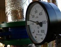
8.5. Pressure measurements When performing testing of pipelines for strength and tightness should be made according to the two (one-control) system at the prescribed manner (one - control) spring pressure gauges not less than 1.5 with a diameter of the housing of at least 160 mm and a scale with a nominal pressure of 4/3 of the measured.
8.6. Tests of pipelines for strength and tightness (density), their purge, flushing, disinfection must be made according to technological schemes (agreed with operational organizations), regulating technology and equipment for the safety of work (including the borders of the security zones).
8.7. On the results of testing pipelines for strength and tightness, as well as their flushing (purge), these are acts of forms given in mandatory applications 2 and 3.
Hydraulic tests
8.8. Pipeline testing should be performed in compliance with the following basic requirements:
test pressure must be provided at the top point (mark) of pipelines;
the water temperature during testing should be no less than 5 degrees;
with a negative temperature of the outer air, the pipeline must be filled with water with a temperature not higher than 70 degrees and to ensure the possibility of filling and emptying it for 1 hour;
with gradual filling with water from pipelines, air must be completely removed;
the test pressure must be sustained for 10 minutes and then reduced to the worker;
at operating pressure, the pipeline is inspected along its entire length.
8.9. The results of hydraulic tests for strength and tightness of the pipeline are considered satisfactory if there was no pressure drop during their conduct, there were no signs of breaking, leaks or fogging in welds, as well as leaks mainly metal, flange connections, reinforcement, compensators and other pipeline elements , There are no signs of shift or deformation of pipelines and fixed supports.
Pneumatic tests
8.10. Performing pneumatic tests should be made for steel pipelines with a working pressure not higher than 1.6 MPa (16 kgf / sq. Cm) and temperatures up to 250 degrees, mounted from pipes and parts tested for strength and tightness (density) manufacturers In accordance with GOST 3845-75 (while the factory test pressure for pipes, reinforcements, equipment and other products and parts of the pipeline should be 20% higher than the test pressure adopted for the mounted pipeline).
Installation of cast-iron fittings (except for the valves from the ductile cast iron) for the time of testing is not allowed.
8.11. Filling the pipeline with air and pressure lift should be performed smoothly at a speed of no more than 0.3 MPa (3 kgf / sq. Cm) in 1 h. Visual inspection of the track [input to a security (dangerous) zone, but without descent to trench] is allowed at a magnitude Pressure equal to 0.3 test, but not more than 0.3 MPa (3 kgf / sq. cm).
For the period of inspection of the route, the pressure lift must be discontinued.
When the values \u200b\u200bof the test pressure is reached, the pipeline must be designed to align the air temperature along the pipeline length. After alignment of the air temperature, the test pressure is maintained for 30 minutes and then smoothly decreases to 0.3 MPa (3 kgf / sq. Cm), but not higher than the size of the working pressure of the coolant; At the same time, a pressure inspection of pipelines with a mark of defective places is made.
The leakage points are determined by the sound of a seerful air, according to bubbles when coating welded joints and other places with soap emulsion and the use of other methods.
Defects are eliminated only by reducing excess pressure to zero and disconnect the compressor.
8.12. The results of preliminary pneumatic tests are considered satisfactory if there was no pressure drop in the pressure gauge during their conduct, defects were detected in welds, flange connections, pipes, equipment and other elements and pipeline products, there are no signs of shift or strain pipeline and stationary supports.
8.13. Water network pipelines in closed heat supply systems and condensate pipelines must usually be subjected to hydropneumatic flushing.
A hydraulic washing is allowed to re-use flushing water by passing it through time mud, installed in the course of water movement at the ends of the feed and return pipelines.
Flushing, as a rule, should be carried out by technical water. It is allowed to flushing with drinking water with a justification in the project's work project.
8.14. Pipelines of water networks of open heat supply systems and hot water networks need to be washed with a hydropneumatic method of drinking quality water to completely lightening the washing water. At the end of the flushing, pipelines must be disinfected by filling them with water with an active chlorine content at a dose of 75-100 mg / l at a contact time of at least 6 hours. Pipelines with a diameter of up to 200 mm and a length of up to 1 km are resolved, in coordination with local sanitation authorities epidemiological service, chlorination is not subject to watering with water, relevant to the requirements of GOST 2874-82.
After washing, the results of laboratory analysis of samples of wash water must comply with the requirements of GOST 2874-82. The results of washing (disinfection) by the sanitary and epidemiological service are concluded.
8.15. Pressure in the pipeline during washing should be no higher than the worker. Air pressure during hydropneumatic flushing should not exceed the operating pressure of the coolant and be no higher than 0.6 MPa (6 kgf / sq. CM).
Water velocities for hydraulic flushing should be not lower than the calculated coolant velocity indicated in the working drawings, and with hydropneumatic - exceed the calculated at least 0.5 m / s.
8.16. Steam pipelines must be produced by steam with a discharge into the atmosphere through specially installed purge nozzles with shut-off reinforcement. To warm the steering pipes, all launcher drains should be opened before purging. The heating rate should ensure the absence of hydraulic shocks in the pipeline.
The velocity of the steam when the purge of each site should be at least working velocities at the calculated coolant parameters.
9. Environmental Protection
9.1. In the construction of new, expanding and reconstruction of existing thermal networks measures for the protection ambient It should be taken in accordance with the requirements of SNiP 3.01.01-85 and this section.
9.2. Not permitted without coordination with the relevant service: to produce earthworks at a distance less than 2 m to the trunks of trees and less than 1 m to the shrub; Moving cargo at a distance less than 0.5 m to crowns or tree trunks; Storage of pipes and other materials at a distance less than 2 m to the trunks of trees without a device around them temporary enclosing (protective) structures.
9.3. Washing pipelines by hydraulically should be performed with reuse of water. Emptying pipelines after washing and disinfection should be in place indicated in the project manufacturing project and coordinated with the relevant services.
9.4. The territory of the construction site after the end of construction and installation works should be cleaned of garbage.
Appendix 1. Act of the extension of compensators
ATTACHMENT 1
Mandatory
g .________________________ "_____" _________________ 19 _____ g.
Commission composed:
(surname, name, patronymic, position)
_____________________________________________________________,
1. A stretching of the compensators listed in the table was presented to the examination and acceptance, on the site from the camera (picket, mines) No. _______ to the camera (picket, mines) No. _______.
Compensator number | Drawing number | Type of compensation | Stretching magnitude, mm | Temperature |
|
according to the drawings | design | actual | air, hail |
||
2. Works are performed by design and estimate documentation ____________
_______________________________________________________________
Commission decision
The works are made in accordance with design and estimate documentation, government standards, construction regulations and regulations and meet the requirements of their acceptance.
(signature)
(signature)
Appendix 2. Act of testing pipelines for strength and tightness
Appendix 2.
Mandatory
g ._____________________ "_____" ____________ 19 ____ g.
Commission composed:
representative of the construction and assembly organization _________________
_____________________________________________________________,
(surname, name, patronymic, position)
representative of the technical supervision of the customer _____________________
_____________________________________________________________,
(surname, name, patronymic, position)
representative of the Operational Organization ______________________
_____________________________________________________________
(surname, name, patronymic, position)
made an inspection of work performed ___________________________
_____________________________________________________________,
(Name of a construction and installation organization)
and amounted to this act of the following:
1. To examination and acceptance is presented ________________
_____________________________________________________________
(hydraulic or pneumatic)
pipelines, tested for strength and tightness and listed in the table, on the site from the camera (picket, mines) No. ________ to the camera (picket, mines) No. _________ RUIDS ___________
Length __________ m.
(pipeline name)
Pipeline | Test pressure | Duration, Min. | Outer inspection at pressure, MPa (kgf / sq. CM) |
2. Works are performed by design and estimate documentation __________________
_____________________________________________________________________
(Name of the project organization, drawings numbers and date of their compilation)
Commission decision
Representative of the construction and assembly organization ________________
(signature)
Representative of the technical supervision of the customer _____________________
(signature)
(signature)
Appendix 3. Act of the washing (purge) of pipelines
Appendix 3.
Mandatory
g ._______________________________________ "_____" _______________ 19 _____ g.
Commission composed:
representative of the construction and assembly organization ________________
_____________________________________________________________,
(surname, name, patronymic, position)
representative of the technical supervision of the customer _____________________
_____________________________________________________________,
(surname, name, patronymic, position)
representative of the Operational Organization _____________________
_____________________________________________________________
(surname, name, patronymic, position)
made an inspection of work performed ____________________________
_____________________________________________________________,
(Name of a construction and installation organization)
and amounted to this act of the following:
1. Flushing (purge) of pipelines on the plot from the camera (picket, mines) No. __________ to the camera (picket, mines) No. ______ tracks ___________________________________________________________________________________________________________________________________________________________________________________________________________________________________
_____________________________________________________________________________________
(pipeline name)
length ___________ m.
Flushing (purge) produced ________________________________
_____________________________________________________________.
(Name of the environment, pressure, consumption)
2. Works are performed by design and estimate documentation _________________
____________________________________________________________________
_____________________________________________________________________.
(Name of the project organization, drawings numbers and date of their compilation)
Commission decision
Works are performed in accordance with design and estimate documentation, standards, construction standards and regulations and meet the requirements of their acceptance.
Representative of the construction and assembly organization ________________
(signature)
Representative of the technical supervision of the customer _____________________
(signature)
Representative of the operational organization _____________________
(signature)
The text of the document is drilled by:
official edition
M.: CITP Gosstroy USSR, 1986
4.2. Rules for testing pipelines of thermal networks when accepting them into operation 4.2.1. All newly mounted pipelines of thermal networks before commissioning should be subjected to hydraulic tests in order to verify the strength and density of pipelines and their elements, including all welded and other connections. Hydraulic tests are subject to: a) all elements and parts of pipelines; Their hydraulic test is not mandatory if they were subjected to 100% control of ultrasound or other equivalent method of non-destructive flaw detection; b) blocks of pipelines; Their hydraulic test is not mandatory if all the components of their elements were tested in accordance with clause 4.2.1, and, and all the welded joints performed during their manufacture and installation are tested by non-destructive flaw detection methods (ultrasound or radiography along the entire length); c) pipelines of all categories with all the elements and their reinforcement after the end of the installation. 4.2.2. Permits hydraulic test Separate and prefabricated elements together with the pipeline, if in the manufacture or installation it is impossible to test them separately from the pipeline. 4.2.3. Hydraulic testing of underground pipelines laid in non-recovery channels and trenches should be made twice (preliminary and final). Testing pipelines available to inspection during operation (laid above and in passing channels) can be made once after the installation is completed. 4.2.4. Preliminary hydraulic testing of pipelines should be carried out by separate areas after their welding and laying on constant supports before installing equipment on them (gland, bellows compensators, valves) and channel overlapping of channels and feedback of the pipeless gasket pipelines and channels. Feed and return pipelines must be tested separately. 4.2.5. The minimum value of the test pressure during hydraulic testing of pipelines, their blocks and individual elements should be 1.25 operating pressure. Working pressure for pipelines of thermal networks should be taken in accordance with the requirements. Fittings and fittings of pipelines must be subjected to hydraulic test pressure testing in accordance with. 4.2.6. The maximum value of the test pressure is set by calculating the strength on NTD, coordinated with the Gosgortkhnadzor of Russia. The value of the test pressure chooses the design organization (manufacturer) within the limits between the minimum and maximum values. 4.2.7. The hydraulic test must be carried out in the following order: the test section of the pipeline turn off from the current networks; At the highest point of the area of \u200b\u200bthe test pipeline (after filling it with water and the air shutter), establish a test pressure; Pressure pressure should be enhanced smoothly; The rate of pressure lifting should be indicated in the NTD to make the pipeline; To withstand the pipeline under a test pressure of at least 10 minutes, after which it smoothly reduce the pressure to the worker and at the same time pressing a thorough inspection of the pipeline throughout the entire length. 4.2.8. With a significant surpass of geodesic openings on a test area, the value of the maximum allowable pressure at its lower point should be coordinated with the design organization to ensure the strength of pipelines and stability of fixed supports. Otherwise, the test must be performed in separate areas. 4.2.9. For hydraulic testing, water should be applied with a temperature not lower than plus 5 ° C and not higher than plus 40 ° C. Hydraulic testing of pipelines should be carried out at a positive ambient temperature. 4.2.10. Pressure measurement should be made on two pressure gauges, one of which must be control. The pressure should increase and decrease gradually. When testing pipelines, spring manometers should be applied to the territorial bodies of the State Standard of Russia. The use of pressure gauges with overdue validity periods is not allowed. Spring manometers must have accuracy class not less than 1.5, the diameter of the housing is at least 150 mm and the scale on the nominal pressure is about 4/3 of the measured. 4.2.11. The pipeline and its elements are considered to be withstanding the hydraulic test, if not detected: leaks, sweating in welded compounds and mainly metal, visible residual deformations, cracks and signs of gap. 4.2.12. Hydraulic reinforcement tests should be made before it is installed on the pipeline. Tests are divided into two main types; Tests for strength and metal density; Tests for the tightness of mobile and fixed connections of compounds (stuffing devices, locking bodies, etc.). Hydraulic crimping reinforcement is performed by test pressure in accordance with. 4.2.13. The final hydraulic test should be made after the completion of construction and installation works, the installation of all equipment (valves, compensators, etc.). The minimum value of the test pressure should be 1.25 operating pressure (see clause 4.2.5). All partitioning valves and valves on the branches of the test thermal network must be open. The time of exposure of the pipeline and its elements under test pressure should be at least 10 minutes, after which the pressure smoothly drops to the worker and a thorough inspection of the pipeline over its entire length is performed. The feed and return pipelines are tested separately. The test results are considered satisfactory if during their conduct there was no decrease in pressure on the pressure gauge and not found signs of gap, leaks or fogging in welds, leaks or fogging in the housings and seals of reinforcement, in flange compounds, etc.
5. Start of thermal networks
5.1. General provisions 5.1.1. All pipelines on which are distributed by pipeline owner enterprises based on the documentation submitted by the installation organizations and manufacturers, the passport of the established form should be compiled (see Appendix 15). 5.1.2. Pipelines III category with conditional passage of more than 100 mm, as well as pipelines IV category with a conditional passage of more than 100 mm, located within the buildings of thermal power plants and boiler rooms, must be recorded before starting to work in the government bodies of the Russian Federation. Other pipelines to be registered are subject to registration at the enterprise (organization), which is the owner of pipelines. The procedure for registering pipelines in the organs of the Gosgortkhnadzor of Russia and the necessary technical documentation are given in. (Modified edition, change No. 1) 5.1.3. Starting heat networks is made by a start-up team led by the head of the launcher. Start should be done on a work program approved by the main engineer of OETS. For newly built trunk heat networks, which are directly from the source of thermal energy source, the program must be coordinated with the main engineer of the heat source. The work program before starting should be transferred: to the head of the launcher; Duty dispatcher OETS; chief shift of the source of thermal energy; on duty engineer of the OEC operational district. The program of starting the heat network should include: a diagram of the pumping and heating installation of the heat source and its mode when the network starts on a separate, clearly delineated over time, stages; operational scheme of the heat network during starting; Priority and order of starting each individual highway or plot; the time of filling of each highway taking into account its volume and fill speed; the estimated static pressure of each completed highway and the influence of this pressure on adjacent network pipelines; The composition of the launch brigade, the arrangement and obligations of each performer during each start stage; Organization and means of communication of the head of the launcher with the OETTs on duty officer, on duty engineer of the operational area, on duty engineer of the source of thermal energy, as well as between individual members of the brigade. 5.1.4. Before starting, a thorough inspection of the heat network should be carried out, the serviceability of all equipment was checked, the acts of acceptance, testing tests and density, washing newly built and repaired network sections. All defects of pipelines, reinforcement, compensators, supports, drainage and pumping devices, air control, control and measuring instruments, as well as hatches, stairs, brackets and other identified as a result of the network inspection should be eliminated before starting start. 5.1.5. Before launch, the head of the startup team is obliged to personally instruct all the staff participating in the start, to give each member of the start-up team specific instructions in accordance with the place of work and possible changes in the regime, as well as instructions on safety regulations for all launchers. 5.1.6. The head of the launcher, making sure the serviceability of the entire equipment, reports the readiness of the operating district engineer, and he, in turn, reports to the OETTC dispatcher on the readiness of the heating network to the launch. After receiving from the duty engineer of the operating area and the duty engineer of the heat source of the heat energy, the equipment readiness of the Equipment to the launch of the OETS Dispatcher allows the duty engineer of the heat source and duty engineer of the operational area to start launching the network in accordance with the program. Regardless of the approved program and graphics, the heat network launch without permission of the OETTs duty officer, this immediately before starting, is not permitted. 5.1.7. The head of the launcher must monitor the progress of filling, heating and drainage pipelines, the state of reinforcement, compensators and other elements of the equipment. In the event of any problems or damage to the equipment, the head of the launcher must take measures to immediately eliminate these faults, and in case of the impossibility of eliminating or occurring serious damage (joint breaking, the destruction of the reinforcement, the disappearance of the fixed support, etc.) - immediately Redets the termination of the start. On the progress of launchers, the head of the launch brigade must be reported by a duty engineering engineer of the operational area, and in exceptional cases - directly to the OETS duty dispatcher. 5.1.8. The OETTS Duty Manager and the operating area duty engineer must record the time of individual start-up operations, the instrument testimony, the condition of the heat network equipment, as well as all the problems that arise and retreat from the normal start-up program. 5.1.9. At the end of the start, the head of the launch brigade reports on this duty engineer of the operating area to the head of the OET operational district and makes entry in the operational journal of the OETs operational district. The duty engineer of the operating area immediately reports the onset dispatcher of the OEET on the end of the launcher. 5.2. Starting a water heat network 5.2.1. Filling the heat network with water 5.2.1.1. Filling the heat network with water and the establishment of circulation mode should, as a rule, be carried out before the heating period at the positive outdoor air temperatures. 5.2.1.2. All pipelines of the heat network regardless of whether they are in operation or in reserve should be filled with chemically purified, deaerated water. The emptying of pipelines is made only at the time of repair, at the end of which pipelines after hydraulic testing for strength and density and flushing should be immediately filled with chemically purified by deaerated water. 5.2.1.3. Thermal network pipelines should be filled with water with water not higher than 70 ° C . Filling pipelines with water directly from the tanks of atmospheric type deaerators in the absence of fuel coolers should be made either after cooling the water in them to 70 ° C, or by mixing the water and reverse pipelines of previously filled networks with such a calculation so that the total temperature of the mixture is not higher 70 ° С. 5.2.1.4. Filling pipelines should be produced by water by pressure not exceeding the static pressure of the fill part of the thermal network by more than 0.2 mpa (2 kgf / cm 2). To avoid hydraulic blows and better air removal from pipelines, the maximum wateral water flow (G in m 3 / h) when filling the pipelines of the thermal network with a conditional diameter (D Um) should not exceed:So, work on the construction of pipelines of the thermal network is completed. Before proceeding with the insulating operations, pipelines must be subjected to testing and tightness. The results of these tests are introduced into the Act, provided for by SNiP 3.05.03-85 "Heat Networks". The full name of the act - act on testing pipelines for strength and tightness.
When filling out the act, the first thing is indicated by the place of testing (name of the city or other settlement), as well as the approval date of the act.
Then we enter the data on the composition of the Acceptance Commission. The commission, as a rule, includes representatives of a construction and installation organization, operational organization, as well as a representative of the technical supervision of the Customer. More details with the relationship system of participants in the construction process can be found. In mandatory, we specify the last name, first name and patronymic of each representative, as well as a position in the organization.
Next, you must specify what method was carried out - hydraulic or pneumatic. By the way, and at that and another method of testing the act is made in the same way. In the next, we specify the boundaries (between cameras, pickets or mines) and the length of the test site.
Based on the data obtained when testing, the Acceptance Commission makes conclusions about the compliance or inconsistency of the mounted pipelines of the thermal network of design and estimate documentation, state standards, construction norms and rules, and the solution is made - if the pipeline asked the test or not.
After completion of the test, the act is signed by all members of the Commission. The change in the shape of the act and deviation from it is not allowed.
As we see, the filling process act on testing pipelines of the thermal network Not complicated, and if you still have any questions, I boldly ask them in the comments, and we will try to respond promptly. Be sure to subscribe to our resource in social networksand receive new recommendations for the conduct of executive documentation among the first.
Custom search
Thematic and inchothematical publications of the articles of the site.
This section of the site presents the publications of thematic articles on heat supply and thermal power engineering, as well as, inchothematical articles on construction, production and industrial equipment.
Hydraulic testing of pipelines.
Hydraulic testing of thermal networks produced twice: first check the strength and density of heat pipes without equipment and reinforcement, after the entire heat pipe, which is ready for operation, with installed mud, valves, compensators and other equipment. Repeated check is needed because with mounted equipment and fittings heavier to check the density and strength of welded seams.
In cases where, when testing heat lines without equipment and reinforcements, there is a drop in the instrument pressure, which means that welds Lovely (naturally, if there are no fistula, cracks, etc. in the pipes themselves. The pressure drop when testing pipelines with installed equipment and reinforcement may indicate that in addition to the joints are made with defects even gland seals or flange connections.
With a preliminary test, it is checked on density and strength not only welds, but also the walls of pipelines, because It happens that the pipes have cracks, fistula and other factory defects. Tests of the mounted pipeline must be performed before installation of thermal insulation. In addition, the pipeline should not be covered or closed with engineering structures. When the pipeline is welded from seamless solid-dimensional pipes, it can be placed in the test already isolated, but only with open welded joints.
With the final test, the connection of the compound of individual sections is to be checked (in cases of testing with parts by parts), welded seams of mud and gland compensators, equipment housing, flange connections. During check, the seals must be compacted, and sectional valves are fully open.
The need for two tests of the heating industry is also caused by the fact that in areas of high length, check the entire heat pipeline at a time is not possible. I would have to leave the open trench for a long time. In this regard, the individual sections of the heat networks are tested before frustration, as they are prepared. The length of the test site depends on the construction time on the individual sections of the route, from the presence of manual, hydraulic or mechanized presses, filled units, piston pumps, water source power (river, pond, lake, water supply), the conditions of production, terrain, etc. .
With hydraulic testing of thermal networks, the sequence of work is such:
- carry out cleaning of heat lines;
- set pressure gauges, plugs and cranes;
- water and hydraulic press are connected;
- fill pipelines with water to the required pressure;
- inspection of thermal pipelines and mark the places where defects were detected;
- eliminate defects;
- produce a second test;
- disconnect from the water supply and produce water descent from pipes;
- Remove the pressure gauges and plugs.
To fill the pipelines of water and good removal from air pipes, the plumbing is attached to the bottom of the heat pipe. Near each air crane, you must set the duty. At first, only air comes through the air, then the air-water mixture and, finally, only water. Upon reaching the exit only water, the crane overlaps. Further, the tap is two or three times periodically open to the full release of the remaining part of the air from the upper points. Before starting filling the thermal network, all air workers must be discovered, and drainage to close.
The test is carried out by pressure equal to the working with a coefficient of 1.25. Under the workers understand maximum pressurewhich may arise in this area during operation.
In cases of testing heat resistant without equipment and reinforcement, pressure is raised to the estimated and maintain it for 10 minutes, while controlling the pressure drop, after it reduces it to the worker, the inspection of welded connections is inspected and the joints are inspected. Tests are considered satisfactory if there is no drop in pressure, there are no leaks and dukes.
Tests with installed equipment and reinforcement are carried out with an excerpt for 15 minutes, the inspection of flange and welded joints, fittings and equipment, gland seals, are reduced to the worker after pressure. Tests are considered satisfactory if the pressure drop does not exceed 10% for 2 hours. Test pressure checks not only the tightness, but also the strength of equipment and pipeline.
After testing, water must be removed from the pipes completely. As a rule, water testing does not undergo special training and can reduce the quality of the network water and be the cause of corrosion of the inner surfaces of pipes.
Who is interested in the acquisition of housing, the realtor of elite real estate will help