Hydraulic tests are carried out in accordance with SNiP. After their completion, an act is drawn up indicating the performance of the system.
They are performed at different stages of the operation of communications. The check parameters are calculated for each system separately, depending on its type.
Content of the article
Why and when to carry out hydraulic tests?
Hydraulic testing is a type of non-destructive testing that is carried out to check strength and density pipeline systems... All operating equipment is exposed to them at different stages of operation.
In general, there are three cases in which tests must be carried out without fail, regardless of the purpose of the pipeline:
- after the completion of the production process for the release of equipment or parts of the pipeline system;
- after the completion of the installation work of the pipeline;
- during the operation of the equipment.
Hydraulic testing is an important procedure that confirms or refutes the reliability of an operating pressure system. This is necessary to prevent accidents on highways and preserve the health of citizens.
The procedure for hydraulic testing of pipelines in extreme conditions is being carried out. The pressure under which it passes is called the test pressure. It exceeds the usual working pressure by 1.25-1.5 times.
Features of hydraulic tests
Test pressure is supplied to the pipeline system smoothly and slowly so as not to provoke water hammer and the formation of accidents. The magnitude of the pressure is determined not by eye, but by a special formula, but in practice, as a rule, it is 25% more than the working pressure.

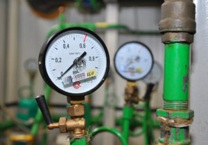
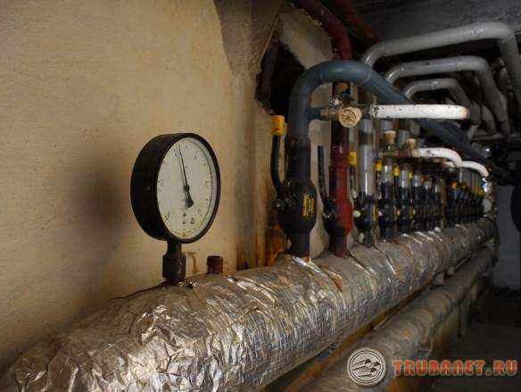
The force of the water supply is monitored on pressure gauges and measurement channels. According to SNiP, jumps in indicators are allowed, since it is possible to quickly measure the temperature of the liquid in the pipeline vessel. When filling it, it is imperative to monitor the accumulation of gas in different parts of the system.
This possibility should be ruled out at the initial stage.
After filling the pipeline, the so-called holding time begins - the period during which the equipment under test is under increased pressure. It is important to ensure that it is on the same level during aging. After its completion, the pressure is minimized to the working state.
While the test is in progress, no one should be near the pipeline.
The operating personnel must wait in a safe place, as checking the functionality of the system can be explosive. After the end of the process, the results are evaluated in accordance with SNiP. The pipeline is inspected for, metal explosions, deformations.
Hydraulic test parameters
When checking the quality of the pipeline, it is necessary to determine the indicators of the following work parameters:
- Pressure.
- Temperatures.
- Exposure time.
The test pressure lower limit is calculated using the following formula: Ph = KhP... The upper limit should not exceed the sum of the total membrane and bending stresses, which will reach 1.7 [δ] Th. The formula is deciphered as follows:
- P is the design pressure, the parameters of which are provided by the manufacturer, or the working pressure if the tests are carried out after installation;
- [δ] Th is the rated voltage that is allowed at the test temperature Th;
- [δ] T is the allowable stress at the design temperature T;
- Kh is a conditional coefficient that takes on a different value for different objects. When checking pipelines, it is 1.25.
The water temperature should not fall below 5˚С and not rise above 40˚С. The only exceptions are those cases when the temperature of the hydro component is specified in technical conditions the object under study. Be that as it may, the air temperature during the test should not fall below the same 5˚С.
The holding time must be indicated in the project documentation for the facility. It should not be less than 5 minutes. If the exact parameters are not provided, then the holding time is calculated based on the thickness of the pipeline walls. For example, with a thickness of up to 50 mm, the pressure test lasts at least 10 minutes, with a thickness of over 100 mm - at least 30 minutes.
Testing fire hydrants and water supply lines
A hydrant is an equipment responsible for the quick elimination of fire ignitions, so it must always be in working order. The main task of fire hydrants is to provide the optimal amount of water to fight a fire at its initial stage.
Pressure pipelines are checked in accordance with SNiP B III-3-81.
Pipes made of cast iron and asbestos are tested with a pipeline length of no more than 1 km at a time. The polyethylene mains of the water supply are checked in sections of 0.5 km. All other water supply systems are checked in sections of no more than 1 km. The holding time for metal water supply pipes must be at least 10 m, for polyethylene pipes - at least 30 m.
Heating systems testing
Heating networks are checked immediately after the completion of their installation. Heating systems are filled with water through the return pipe, that is, from the bottom up.
With this method, liquid and air go in the same direction, which, according to the laws of physics, with promotes the removal of air masses from the system. The drainage occurs in one and the same way: through the outlets, tank or plungers of heating systems.
If the heating networks are filled too quickly, air pockets may appear due to the filling of the risers with water faster than the heating devices of heating systems. pass under the lower working pressure of 100 kilo Pascal and the test pressure - 300 kilo Pascal.
Heating networks are checked only when the boiler and expansion tank are disconnected.
Heating systems are not monitored during winter. If they have worked without breakdowns for up to about three months, then the acceptance of heating networks into operation can be carried out without hydraulic tests. When checking closed heating systems, the control work must be carried out before the furrows are closed. If insulation of heating networks is planned, then - before its installation.
According to SNiP, after the end of the tests of heating systems, they are washed, and at their lowest point a coupling with a cross section of 60 to 80 mm2 is mounted. Water is drained through it. Washing heating networks carried out with cold water several times, before acquiring transparency. Heating systems are approved if, within 5 minutes, the test pressure in the pipeline does not change by more than 20 kilo Pascal.
Hydraulic test of the heating and water supply system (video)
Hydraulic tests of heating networks and water supply systems
After the completion of hydraulic tests of heating systems according to SNiP, an act of hydraulic tests of heating networks and water supply systems is drawn up, indicating the compliance of the pipeline parameters.
According to SNiP, its form contains the following information:
- title of the position of the head of the enterprise that provides maintenance of heating networks;
- his signature and initials, as well as the date of verification;
- information about the chairman of the commission, as well as its members;
- information on the parameters of heating networks: length, names, etc .;
- conclusions about the control, the conclusion of the commission.
Adjustment of the characteristics of heating lines is carried out by SNiP 3.05.03-85. According to the specified SNiP, its the rules apply to all highways, which transport water with temperatures up to 220˚С and steam - up to 440˚С.
For the documentary completion of hydraulic tests of a water supply system, an act is drawn up for an external water supply system in accordance with SNiP 3.05.01-85. According to SNiP, the act contains the following information:
- system name;
- the name of the technical supervision organization;
- data on the value of the test pressure and test time;
- pressure drop data;
- the presence or absence of signs of damage to the pipeline;
- date of inspection;
- withdrawal of the commission.
The act is certified by a representative of the supervision organization.

Upon completion of installation, all process pipelines are tested for strength and tightness in accordance with the requirements of SNiP. Pipelines can be tested for strength and tightness hydraulically or pneumatically.
Pneumatic testing of the pipeline for strength is carried out in cases where it is impossible to conduct a hydraulic test (negative ambient temperature, lack of water at the site, dangerous stresses in the pipeline and supporting structures from the weight of water), and also when the project provides for testing pipelines with air or inert gas.
Testing of pipelines is relied on under the direct supervision of the work manufacturer or foreman in strict accordance with the instructions in the project and special instructions and requirements. Gosgortekhnadzor, as well as in compliance with safety regulations.
Before starting work on testing, the pipeline line is conditionally divided into separate sections, its external inspection is performed, technical documentation is checked, air and drain valves, pressure gauges, temporary plugs are installed and a temporary pipeline is connected from filling and pressure testing. aggregates. The tested pipeline is disconnected from devices, machines and untested pipe sections using special plugs with shanks. The use of shut-off valves installed on the pipeline for this purpose is not allowed. Connect the pipeline to be tested to a hydraulic press, pump, compressor or air network that creates the required test pressure through two shut-off valves.
Pressure gauges used for testing pipelines must be checked and sealed. Pressure gauges must meet an accuracy class of at least 1.5 in accordance with GOST 2405-63, have a body diameter of at least 150 mm and a scale for a nominal pressure of about 4/3 of the measured pressure. Thermometers used for pneumatic testing must have a graduation value of not more than 0.1 gr.C.
By hydraulic test, pipelines are checked simultaneously for strength and tightness.
Strength test pressure installed by the project; it should be equal to:
- For steel pipelines at operating pressures up to 4 kgf / cm 2 and for pipelines designed to work with wall temperatures above 400 ° C, 1.5 operating pressure, but not less than 2 kgf / cm 2;
- For steel pipelines at operating pressures of 5 kgf / cm 2 and above 1.25 operating pressure, but not less than the operating pressure plus 3 kgf / cm 2;
- For other pipelines 1.25 working pressure, but not less than 2 kgf / cm 2 for cast iron, vinyl plastic, polyethylene and glass;
- 1 kgf / cm 2 for pipelines made of non-ferrous metals and alloys;
- 0.5 kgf / cm 2 for faolite pipelines.
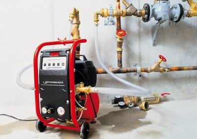
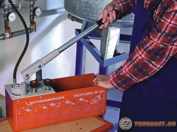
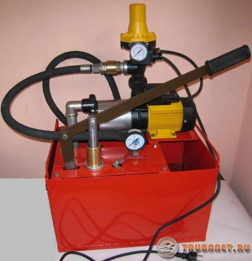
To create the necessary pressure in the pipeline during hydraulic testing, plunger mobile pumps (NP600, GN1200400), piston hand pumps (TN500, GN200), hydraulic presses (VMS45M), gear drive (NSh40), as well as operating pumps are used.
The hydraulic test process consists of following operations: connecting a hydraulic pump or press; installation of pressure gauges; filling the pipeline with water (in this case, the air vents should be kept open until water appears in them, which indicates the complete displacement of air from the pipeline); inspection of the pipeline when filling it with water in order to detect leaks through cracks and leaks in the joints; creating the required test pressure with a hydraulic press or pump and holding the pipeline under this pressure; reduction of pressure to working and repeated inspection of the pipeline; emptying the pipeline; removal of the hydraulic pump and pressure gauges.
Under the test pressure, all pipelines withstand within 5 minutes, with the exception of glass, which is kept for 20 minutes.
Inspect pipelines after reducing the pressure in the pipeline to the working one. When inspecting steel pipelines welds at a distance of 1520 mm on both sides of them, they are easily tapped with a rounded hammer weighing no more than 1.5 kg, and when inspecting pipelines made of non-ferrous metals with a wooden hammer weighing no more than 0.8 kg. Do not tap on pipelines made of other materials.
Hydraulic test results strength and density are considered satisfactory if during the test there was no pressure drop across the pressure gauge, and in welds, flange connections and glands are free from leaks and sweating. If the test results are unsatisfactory, the defects should be eliminated and the test repeated.
At a negative ambient temperature, the hydraulic test of the pipeline is carried out, providing the necessary measures against freezing of water, especially in the drain lines (preheating or adding an aqueous solution of calcium chloride).
After a hydraulic test in the autumn-winter time, the pipelines are blown with compressed air to completely remove the water. Blow out very carefully to avoid stagnation of water at the lowest points of the pipeline.
Hydraulic testing of water supply pipelines usually becomes the next stage after completion of the installation work. This stage is indispensable when working with networks that work under pressure. In this procedure, a pump is used to build up pressure.
Which contributes to the timely identification of defects. After carrying out a hydraulic test of the pipeline, they proceed to drawing up an act. Operation of the pipeline becomes available only after signing it.
By pursuing hydraulic tests water supply pipelines, experts check several indicators at once:
- Defective areas detection.
- Tightness.
- Reliability.
Heating testing is carried out before the newly built facility is put into operation. This applies not only to the introduction of new communications, but also to its overhaul.
If defects are found, they are eliminated as soon as possible. The tests are repeated until the results of the work are deemed positive.
The pipelines themselves are tested in two passes.
- The preliminary ones come first.
- They are followed by the final ones.
The first stage involves pumping water into the pipeline at high pressure. The main thing is that the pressure is one and a half times greater than the usual operating indicators.
IMPORTANT! Hydraulic testing of water supply pipelines is also prescribed before finishing the interior. Specially trained people are responsible for hydraulic testing of water supply systems.
The underground sections of the pipeline are completely closed before the start of the final tests. At this stage, it is necessary to complete all installation work.
But the installation of plumbing fixtures has not yet begun. During these measures, the pressure is increased by 1.3 times in comparison with the usual one.
The technique allows for additional rules.
- Hydraulic checks of water supply systems should be carried out only 24 hours after the installation is completed. Temperature the environment must be above zero.
- When carrying out this event, the pipes are completely filled with water. Until it reaches the top of the risers. Before this, the condition of the pipes undergoes a visual inspection for control. If noticeable flaws are identified, they are corrected immediately. The system is considered to have passed the test if no leaks occur within 20 minutes of operation. And if the water maintains the previously marked level.
Watch the video
Under what conditions is it necessary to carry out a hydraulic check of pipelines?
It is necessary to realize how complicated the procedure is for hydraulic testing of plumbing systems. The reliability of the structure itself and its quality largely depend on the literacy of this procedure. Therefore, the work is trusted only by specialists with the appropriate classification.
The requirements for the test work themselves include several items. This is required by any technique.
- All points of use in the riser are switched on at the same time to check efficiency. But the need for this stage is determined individually, at each of the enterprises separately.
- The condition of heated towel rails is tested when the hot water supply is checked.
- Temperature measurements are carried out only at the extreme sections in the system. Water is filled with predefined characteristics.
- The liquid must be completely drained after the completion of all stages of the activities.
- The filling of pipelines begins from the lower floors, gradually moving to the upper ones. Then the air will be correctly expelled from the pipes. And there is no danger of air pockets in the pipeline.
- The first stage in filling the water supply system affects only the main section. Only at the next stages are they transferred to small local networks, separate risers.
- On the street or indoors during work, the temperature should not fall below +5 degrees.
Carrying out the procedure at the preliminary stage
Video: Hydraulic Inspection of Water Supply and Heating
Building codes govern the order in which inspections are carried out.
- First, the water supply is filled with liquid. And left in this state for two hours.
- Go to the creation of increased pressure for two hours. This is very slow. At this stage, it is already possible to identify a number of leaks.
- The pressure is reduced until they reach the calculated indicators. Then proceed to the study of the general condition of the track.
- This pressure is maintained for thirty minutes or more. Without such a step, the deformed shape of the pipes simply cannot stabilize.
- The next stage is to shut off the taps at the entrances. The water is slowly drained using a pressure pump.
- The track is checked for serious problems.
IMPORTANT! It is better to know in advance what pressure is standard for a particular line, according to SNiP. This will allow the readings to be verified against the limits shown on the instruments themselves. And follow the technique exactly.
What is the final hydraulic test of the water supply lines?
Such hydraulic checks of water supply pipelines are carried out after the completion of installation of plumbing fixtures for hot water.
- They start by pumping a working pressure into the water supply system. It must be raised to the initial mark if the indicator has dropped by 0.02 MPa.
- Before the test readings, the head rises in ten minutes. The system remains in this state for two hours.
 It is organized before it is installed water fittings... And here it is assumed that the pipeline will be completely filled with water. Next, adhere to the following sequence of actions.
- Shut off the valve that connects the hot water supply system to external networks.
- Hoses for draining contaminated water into the sewer are connected to the drain taps, which are responsible for emptying the risers.
But even after such washing, there is no guarantee that all the debris will be removed. Therefore, specialists develop equipment that increases the effectiveness of this process.
Video: What is a heating system pressure test
Any such device creates a mixture of air and hot water, which is impulsively fed into the pipeline, which requires cleaning. When the mixture passes through the equipment, it is discharged into the sewer. The ripple or feed force can be easily adjusted to lengthen or shorten the timing.
About special equipment for crimping
The design of the pumping mechanism is the main difference between the pump models, without which hydraulic testing of water supply lines according to SNiP becomes impossible.
 This feature allows you to divide into the following groups:
- Membrane.
- Rotary vane.
- Reciprocating.
A manual crimper is the cheapest option, suitable for heating and plumbing circuits in private houses. The operator, using this device, can pump up to three liters of fluid into the system per minute.
Two-stage pumps allow you to solve more serious problems. At the same time, the method of their work remains approximately the same.
On regulation and other features of the process
SNiPs contain all the information related to the conduct of inspections, both for internal and external networks. The industry standards describe the methodology for conducting events at enterprises in a specific field of activity.
This indicator depends on several factors at once:
- The height difference between the top and bottom elements.
- The thickness that the walls have.
- The material from which the pipeline is made.
Video: hydraulic test of heating pipelines
The pressure value according to SNiP usually does not exceed 10 MPa. A specific indicator is individually calculated for each of the types of lines, for certain types of hydraulic tests of water supply systems.
How is the act with the results of work filled in?
The document should display information related to:
- Signs of leakage, reliability in threaded and welded joints, if present. Did drops appear on pipe surfaces and fittings?
- Results of direct verification.
- Ways to eliminate the identified malfunctions.
- Address and date of the inspection. And the names of the citizens who put their signatures on the act. Usually, the signatures are put by the owners of houses or apartments. Or this function is assigned to the representatives of the repair and maintenance organization.
- The project according to which the contour was installed.
- Practical crimping method.
About pressure standards for crimping
When testing water supply, the pressure indicator according to SNiP depends on which indicator is considered to be working for a particular system. In turn, the base materials in the pipes determine the value of the working pressure itself.

No less attention is paid to the radiators used during installation work. When pressure testing is carried out in new systems, the pressure indicator according to GOST is twice the working standard. For existing systems, an excess of 20-50 percent is permissible.
A definite maximum pressure withstands every type of pipes and radiators. This factor must be taken into account when choosing the optimal performance for a particular system. And when choosing the parameters on which the crimping is carried out.
At the input unit, crimping deserves special attention. The minimum required level for such work is 10 atm.
It is impossible to create a parameter of this type without special electric pumps. The result is considered positive if the parameter drops by no more than 0.1 atm in half an hour.
Private houses: we carry out crimping
Private houses involve the use of closed water supply systems. According to GOST, the working pressure indicator for them is a maximum of 2 atmospheres.
When conducting hydraulic tests, it is impossible to do without pumps with manual and electric drives, which help to build up pressure up to 4 atmospheres... Connection to the heating main is permissible.
Video: hydraulic test of cold water systems
Water begins to fill the structure from below, using the drain valve. Next comes the air, it easily pushes the water out. Removal of excess passes through air-type valves mounted at the very top. The same thing happens on every radiator. Or in places where traffic jams appear.
For testing water supply communications, water is used, the temperature of which does not exceed 45 degrees according to GOST.
Independent pressure testing is mandatory if the owner installs the entire pipeline system himself. The procedure is the same as in houses with many apartments.
The level of water hardness for hydraulic testing of water supply pipelines should remain low, if it is then planned to be used as a heat carrier.
The use of melt or rain water is permissible. It is completely drained if no further use is planned.
Additional information about documents
In the act based on the results of the hydraulic test, it is imperative to write about which brand of pressure gauge was used. They also indicate the measurement of pressure readings in the system at the time of verification. They write about how high the measuring device was in relation to the pipe axis.
Video
The pipeline must be disinfected before it is put into service. To do this, use ordinary water, to which active chlorine is added, in an amount of 20-30 grams, according to GOST.
At the next stage, they move on to flushing the pipeline. It is possible to use the liquid from the pipes itself only if the bacteriological analysis is positive. Flushing is carried out as long as it takes to change the liquid inside ten times.
(2
estimates, average: 5,00
out of 5)
Discussion is closed.
Testing of pipelines made of polymeric materials is carried out in accordance with SNiP Sh-29-76 and SN 440-83. Before the start of the test, the pipelines are subjected to external inspection in order to establish the compliance of the installed pipelines with the project and their readiness for testing. During the inspection, they check the condition of the mounting joints, the correct installation of fittings, supports and suspensions, the ease of opening and closing of its locking devices, the correct installation of expansion joints, the possibility of removing air from the pipeline, filling it with water and emptying it after testing.
Tests must be carried out at an ambient temperature of at least minus 15 ° С for LDPE and HDPE pipelines and at least 0 ° С for PVC and PP pipelines, and not earlier than 24 hours after welding or pasting the last joint.
Before testing external pipelines, they must be blown out to clean the internal surface of dirt. Cleaning of the cavity of internal pipelines and pipelines of gas control points is carried out before their installation.
The test method for pipelines should be specified in the project. In the absence of such instructions in the project, a pipeline made of polymeric materials should, as a rule, be tested hydraulically.
Strength and density tests of pipelines are carried out by the installation company in the presence of representatives of the customer and the gas utility, which is fixed by the corresponding act.
The pipeline or its section to be tested is disconnected from the equipment, other pipelines or sections with plugs with shanks, the dimensions of which are given in table. 55. Use for-
porous fittings for disconnecting the tested section of the pipeline are prohibited.
The pressure in the pipeline is controlled by two pressure gauges, one of which is a control one. The pressure gauges must have seals installed by the State Control Laboratories after a check carried out once a year.
Defects found during testing are eliminated after the pressure is reduced and the pipeline is free of water. It is not allowed to tap welded and glue seams during testing. Defective joints made by resistance welding are cut out and in their place "coils" with a length of at least 200 mm are welded. IN Lately repair of defective joints is carried out by welding on the remaining couplings. If necessary, tighten the connections, having previously loosened the tightening of the clamps of the nearest supports. After stretching, the pipeline is again secured. After elimination of all defects, the pipeline is retested. The relevant acts are drawn up on the testing and permission is obtained to connect the installed and tested section (line) of the pipeline to the existing ones.
Tests of pipelines are carried out under the direct supervision of a foreman or another work manager in accordance with the requirements of SNiP II1-4-80 on safety in construction and CM 440-83.
Hydraulic tests. Before carrying out hydraulic tests, it is necessary to carry out preparatory work:
- install devices for air release at the top points of the tested pipeline - "air vents";
- install drainages at the lowest points (water drain); install pressure gauges at the beginning and end of the tested pipeline;
- connect the tested pipeline to a pump or water supply that creates the required pressure and ensures that the pipeline is filled with water;
- take measures against freezing of water, especially in the lower points and drain lines (the use of solutions with a low freezing point or heated water up to 40 ° C for LDPE and PVC pipes and 60 ° C for HDPE and PP pipes).
The tests are carried out in the following sequence. Fill the pipeline with water with open air vents. When water appears, the air vents are closed and the pressure gradually increases to the value required for the strength test. Upon reaching the pressure of a predetermined value, pipelines made of thermoplastics are kept for 15 ... 30 minutes and during this time the pressure is maintained by pumping up water with a pump, since these pipelines are subject to elastic deformation. After stabilization, the pipeline is kept under test pressure for 5 minutes, then the pressure is reduced to working pressure and held for 30 minutes. At this time, an external inspection of the pipeline is carried out, paying special attention to the joints. The working pressure test is a density test.
After the test, open the air vents, outlet or drain (drainage) device and free the pipeline from water. The hydrostatic test results are considered satisfactory if the pressure does not drop during the holding time, and there are no leaks or fogging in the welds and flanged joints and glands.
Simultaneous hydraulic testing of several pipelines mounted on one trestle or supporting structures is performed if these structures are designed for the corresponding loads.
Pipes laid in trenches or impassable channels are tested twice. Before backfilling the trench and installing the fittings, preliminary tests of the pipeline are carried out. The value of the preliminary test hydraulic pressure during the strength test shall be equal to the design working pressure for a given type of pipe, multiplied by a factor of 1.5.
The final hydraulic test of the pipeline is carried out after filling the trench and completing all work on this section of the pipeline, but before installing hydrants, safety valves, instead of which plugs were installed during the tests. The value of the final test hydraulic pressure shall be equal to the design pressure for the given type of pipe, multiplied by a factor of 1.3.
A preliminary hydraulic test of pressure head plastic pipelines is carried out in the following sequence. The pipeline is filled with water and kept without pressure for 2 hours. After that, a test pressure is created in it and maintained for 0.5 hours. Then the test pressure is reduced to the calculated working pressure, kept at this pressure for at least 0.5 hour and an inspection is carried out pipeline. Since the pipeline shell is deformed during the test, it is necessary to pump water to maintain the test or working pressure in the pipeline.
A pressure plastic pipeline is considered to have passed the preliminary hydraulic test if no ruptures of pipes or joints and fittings are found at the test pressure, and at operating pressure there are no visible water leaks or sweating of the joints.
The final hydraulic tests for the density of water supply and sewerage pipelines begin no earlier than 48 hours after filling the trench and no earlier than 2 hours after filling the pipeline with water.
The final hydraulic test is carried out in the following sequence. A pressure equal to the design working pressure for this type of pipes is created in the pipeline, and it is maintained for 2 hours. When the pressure drops by 0.02 MPa, water is pumped up. Then, in at least 10 minutes, the pressure is raised to the test level and maintained for 2 hours. When the pressure drops by 0.02 MPa during this period, water is also pumped up. The water leakage is then determined by measuring the amount of water added to maintain the test pressure.
Hydraulic tests of gravity sewer networks made of polymer pipes are carried out twice: without wells (preliminary) and together with wells (final). Preliminary tests of sewage pipelines must be carried out in separate sections located between the wells, selectively at the request of the customer. If the results of the random test are unsatisfactory, then all sections of the pipeline are subject to testing.
Preliminary tests of sewage pipelines are carried out with an unbacked trench under hydraulic pressure 0.05 MPa with exposure for 15 minutes. If there are no visible water leaks in butt joints it is allowed to maintain the test pressure by pumping water.
The final test of the sewage pipeline together with the wells is also carried out selectively - two adjacent sections with an intermediate well and wells at the ends of the pipeline. The site for final testing is selected at the request of the customer.
The tested section of the pipeline is considered to have passed the density test if the leakage value is less than or equal to the leakage value through the walls and bottom of the wells for 1 m of their depth, corresponding to the permissible leakage value taken per 1 m of the length of concrete or reinforced concrete pipes, the diameter of which is equal to the inner diameter of the wells -dev.
Hydraulic tests of sanitary-technical systems made of polymer pipes are carried out at a positive ambient temperature not earlier than 24 hours after the last welded joint... The value of the test pressure at the lowest point of the pressure pipeline is assumed to be: for pipes of type T - 1.5 MPa; C - 0.9 MPa; SL - 0.6 MPa; L - 0.38 MPa. Hydraulic tests are carried out after filling the pipeline with water and checking the absence of air in it by holding under test pressure for at least 30 minutes and by external inspection of the pipeline. For HDPE and LDPE pipelines, the pressure during the test and inspection period is maintained at a predetermined level with a deviation of no more than 0.05 MPa. The pipeline is considered to have passed the test if no leaks or other defects are found.
Hydraulic tests of internal drainage systems are carried out by filling them with water to the entire height of the risers. Tests are carried out after external inspection of pipelines and elimination of external defects. Hydraulic tests begin 24 hours after the end of welding. The drainage system is considered to have passed the test if, after 20 minutes after it has been filled with water, an external examination does not reveal a leak or other defects, and the water level in the risers does not decrease.
Pneumatic tests of pipelines made of thermoplastics for surface and underground laying are performed:
- at an ambient temperature below 0 ° С;
- if the supporting structures are not designed to fill the pipeline with water;
- if the use of water is unacceptable for technical reasons;
- in the absence of water for testing in the required quantities.
Pneumatic tightness tests can only be performed after a strength test by any method. It is not allowed to carry out pneumatic tests for the strength of pipelines in existing workshops of industrial enterprises, on racks and canals where existing pipelines are located. For pneumatic tests, use air or an inert gas.
The length of the section of the intrashop pipeline subjected to pneumatic testing should not exceed 100 m for a pipeline with a diameter of up to 200 mm, for Z) “more than 200 mm - no more than 75 m. 250 m and for DH over 200 mm - no more than 200 m.
The test pressure for strength is maintained for 5 minutes, after which it is reduced to the working pressure, at which the pipeline is inspected. The pressure during pneumatic testing is raised gradually with inspection of the pipeline when reaching 0.6 test pressure for a pipeline with a working pressure of up to 0.2 MPa and with inspection when reaching 0.3 and 0.6 test pressure for pipelines with a working pressure of over 0.2 MPa ... During pipeline inspection, the pressure build-up stops.
During pneumatic testing of plastic technological pipelines, defects are detected in the following ways: by sound, by coating welded, adhesive and flanged joints with soapy water (emulsion), and halogen leak detectors.
A soap emulsion is prepared from a soap solution with the addition of glycerin (for 1 liter of water, 40 g of soap and up to 10 g of glycerin). During pneumatic tests of plastic pipelines in winter (up to minus 15 ° C), a soap emulsion of the following composition is prepared: technical glycerin - 450 g, water - 515 g and soap powder - 35 g. use halogen leak detectors of various designs.
It is necessary to measure the gas pressure in the pipeline during the test only after the temperature in the pipeline has equalized. In pneumatic tests with pressures up to 0.01 MPa, liquid U-shaped pressure gauges with water filling are used to control pressure, at pressures above 0.01 MPa - U-shaped mercury manometers or spring ones, at a pressure of 0.1 MPa - spring pressure gauges of a class not lower than 1.5. Manometers are installed at the beginning and at the end of the tested section of the pipeline.
The need to test plastic pipelines for density with the determination of the pressure drop and its permissible values are established by the project for pipelines located outside buildings and workshops. In the absence of special instructions in the project, the duration of the tests should be at least 12 hours.
The permissible pressure drop in technological plastic pipelines DH up to 250 mm, transporting toxic substances and located outside buildings, should not exceed 0.1% h of the test pressure; 0.2% h - for pipelines transporting hot and other active gases. For pipelines DH more than 250 mm, the norms of pressure drop during testing are determined by multiplying these values by the coefficient / C = 250 / DBH, where DB „is the inner diameter, mm, of the tested pipeline.
Preliminary and final tests of gravity sewer networks from polyethylene pipes large diameter can be carried out pneumatically. A preliminary test is carried out prior to the final backfilling of the trench. The test pressure of compressed air, equal to 0.05 MPa, is maintained in the pipeline for 15 minutes. At the same time, welded joints are inspected and leaks are detected by the sound of leaking air, by bubbles formed in places of air leakage when soaping the welded joints with a soap emulsion.
The final pneumatic test is carried out with a groundwater level in the middle of the test pipeline of less than 245 kPa. The final pneumatic tests are carried out on sections with a length from 20 to 100 m, while the pressure difference between the highest and lowest points of the pipeline should not exceed 245 kPa. Pneumatic tests are carried out 48 hours after filling the pipeline.
Pneumatic tests are carried out in the following sequence. The compressor creates a pressure P in the pipeline, check the tightness of the plugs and maintain this pressure for 10 minutes. Then, the air supply valve is closed, and after 2 min, the time for the air pressure in the pipeline to drop to the Pi level is measured. The pipeline is considered to have survived pneumatic test if the time during which the test pressure will decrease from the P level to the Pi level will be at least 11 minutes for HDPE pipes with a diameter of up to 700 mm, up to 800 mm - 12 minutes, up to 900 mm - 14 minutes, up to 1000 mm - 16 min, up to 1200 mm - 18 min.
After testing, the pipeline must be flushed or purged in order to remove dirt and foreign particles from it that have entered the pipeline during the installation and welding of field joints. Flushing is carried out with water, and blowing with compressed air or inert gas. Flushing should be carried out with drinking water or industrial water with a temperature of 5 ... 30 ° C at a water velocity in the pipeline of 1 ... 1.5 m / s until the stable appearance of clean water from the outlet pipe or drainage device, the diameter of which should be at least half the diameter of the flushed pipeline. During flushing, the shut-off valves on the pipeline must be open and the valves removed.
The duration of flushing with chlorinated water of pipelines of domestic and drinking water supply, mounted from polyvinyl chloride pipes, should be at least 12 hours.
After flushing, the pipeline is freed of water and, if necessary, purged with compressed air to remove its residues.
The purging of pipelines for technological purposes with compressed air is carried out at operating pressure, preventing a decrease in pressure at the end of the pipeline by more than 0.01 MPa. The duration of the purge is not less than 10 minutes at a temperature not higher than 30 ° C. It is strictly forbidden to blow through plastic pipelines with steam.
After flushing and purging, it is necessary to restore the entire section of the pipeline, remove or plug all fixtures and fittings for testing, flushing or purging. Appropriate acts shall be drawn up on testing, flushing and purging.
Only the correct and reliable functioning of the heating system is able to ensure a calm and normal life of the population in the winter period of the year. Sometimes different kinds happen extreme situations in which the performance of the system may differ materially from civilian conditions. Hydraulic testing of pipelines and pressure testing is necessary to prevent situations that may arise during the heating season.
The purpose of hydraulic tests
As a rule, any heating system works in standard mode. The operating pressure of the coolant in low-rise buildings is mainly 2 atm, in nine-storey buildings - 5-7 atm, in multi-storey buildings - 7-10 atm. In a heat supply system laid underground, the pressure indicator can reach 12 atm.
Sometimes unexpected pressure surges occur, which leads to an increase in pressure in the network. As a result, the heating pipelines are tested, it is necessary to check the system not only for its ability to function under standard normal conditions, but also for its ability to overcome water hammer. 
If, for some reason, the heating system has not been checked, then subsequent hydraulic shocks may result in serious accidents that will lead to the flooding of rooms, equipment, furniture, etc. with boiling water.
Sequence of work
Hydraulic testing of pipelines should be carried out in the following sequence.
- Cleaning of pipelines.
- Installation of taps, plugs and pressure gauges.
- Water is connected and
- The pipelines are filled with water to the required value.
- Inspection of pipelines and marking of places where defects were found are carried out.
- Elimination of defects.
- Conducting a second test.
- Disconnection from the water supply and drainage of water from pipelines.
- Removing the plug and gauges.
Preparatory work
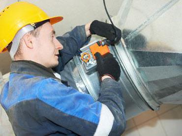
Before performing hydraulic tests of pipelines of heating systems, it is necessary to revise all valves, fill glands on the valves. Insulation is being repaired and checked on pipelines. The heating system itself must be separated from the main pipeline by means of plugs. 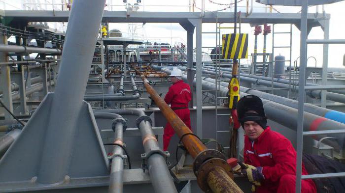
After completing all the necessary manipulations, the heating system is filled with water. With the help of pumping equipment, its indicator is created about 1.3-1.5 times higher than the working one. The resulting pressure in the heating system should be kept for another 30 minutes. If it has not decreased, then the heating system is ready for operation. Acceptance of works on hydraulic testing is carried out by the inspection
and tightness
Preliminary and acceptance hydraulic tests of pipelines (SNiP 3.05.04-85) must be performed in a certain sequence.
Strength
Tightness
- The pressure in the pipeline rises to the test indicator for tightness (P g).
- The start time of the test (T n) is recorded, the initial water level (h n) is measured in the measuring tank.
- After that, the decrease in the pressure indicator in the pipeline is monitored.
There are three options for the pressure drop, consider them.
First
If, within 10 minutes, the pressure indicator decreases by less than 2 marks on the pressure gauge scale, but does not fall below the calculated internal (P p), then the observation can be completed.
Second
If, after 10 minutes, the pressure value drops by less than 2 marks on the manometer scale, then in this case, monitoring the decrease in pressure to the internal (P p) calculated pressure must be continued until it drops by at least 2 marks on the manometer scale.
The duration of observation for should not exceed 3 hours, for cast iron, steel and asbestos-cement pipes - 1 hour. After the specified time has elapsed, the pressure must drop to the design pressure (P p), otherwise the water is discharged from the pipelines into the measuring tank.
The third
If, within 10 minutes, the pressure becomes less than the internal design pressure (P p), then further hydraulic tests of heating pipelines must be suspended and measures must be taken to eliminate hidden defects by maintaining the pipes under the internal design pressure (P p) until a thorough inspection no defects will be detected that will cause an unacceptable pressure drop in the pipeline. 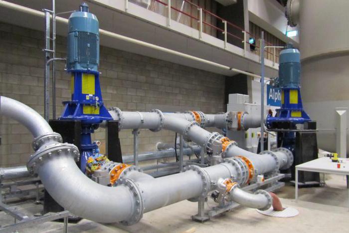
Determination of the additional volume of water
After completing the observation of the drop in the pressure indicator according to the first option and stopping the discharge of the coolant according to the second option, the following should be done.
Drawing up an act
The certificate that all work has been carried out is the act of hydraulic testing of pipelines. This document is drawn up by the inspector and confirms that the work was carried out in compliance with all norms and rules, and that the heating system withstood them successfully.
Hydraulic testing of pipelines can be carried out in two main ways:
- Gauge method - tests are carried out by means of manometers, instruments that record pressure indicators. During operation, these devices show the current pressure in the heating system. Hydraulic testing of pipelines by means of a pressure gauge allows the inspector to check what the pressure was during testing. Thus, the service engineer and inspector check how reliable the tests performed are.
- The hydrostatic method is considered the most effective, it allows you to check the heating system for operability at a pressure that exceeds the average operating indicator by 50%.
Various elements of the system are tested for different times, while hydraulic testing of pipelines cannot last less than 10 minutes. IN heating systems the permissible pressure drop is considered to be 0.02 MPa.
The main condition for the beginning of the heating season is competently conducted and properly executed hydraulic tests of pipelines (SNiP 3.05.04-85), in accordance with the requirements of the current regulatory documentation.