When building pipelines away from water sources, as well as in winter, when the water freezes, pipelines are tested with compressed air.
If, during the final test, it is not allowed to raise the pressure in the pipelines to the test pressure due to safety precautions, then combined tests are carried out: preliminary - pneumatic (compressed air), and final - hydraulic (water pressure).
To conduct a pneumatic test, the following are required: a compressor, two spring pressure gauges - one on the pipe for supplying compressed air from the compressor, the other at the opposite end of the tested section of the pipeline; one-tube liquid pressure gauge; reservoir for liquid pressure gauge (fig. 44).
Preparation of pipelines for pneumatic testing is carried out in the same way as for hydraulic testing.
The length of the test section with the pneumatic method for asbestos-cement, cast iron and steel pipes should not exceed more than 1 km, and for polyethylene - no more than 0.5 km. During the test, the pipes must be covered with soil 30-50 cm above the sheath, and only the joints of the pipelines are allowed to be left open.
Defects in the test section of the pipeline are detected in one of the following ways:
By the sound of leaking air;
By bubbles of a soap emulsion, which is applied immediately before testing for butt joints;
By the smell of leaking odorized air (on any pipelines, except for polyethylene).
An odorant in the form of ammonia, ethyl mercaptan and other gases is added to the air supplied by the compressor during testing.
The pneumatic test is carried out in the same two stages as the hydraulic one: preliminary and final. The final test is a passing test. The pressure in the pipelines during their testing should be increased gradually in steps, 0.2 of the test pressure, at intervals of 5 minutes.
The strength test of steel pipelines at an operating pressure of up to 5 kgf / cm 2 is carried out with a test pressure of 6 kgf / cm 2, and at an operating pressure of over 5 kgf / cm 2 - a test pressure 15% higher than the operating pressure. First, the pressure is increased to the test pressure and the pipeline is kept under it for 30 minutes. Then the pressure is reduced to 3 kgf / cm 2 and the pipeline is inspected.
The final test is carried out in the following order.
1. The pressure is increased again to the test pressure and the pipeline is kept under this pressure for 30 minutes. Then the pressure is reduced to 0.5 kgf / cm 2 and the pipeline is kept under this pressure for 24 hours.
2. The pressure is increased again to 3000 mm of water. Art. (when filling the liquid manometer with water) or up to 3450 mm of water. Art. (when filling it with kerosene).
The pipeline is kept under this pressure for a certain time, which is established by standards for pipes made of different materials and different diameters. After this time, the pressure in the pipeline and barometric pressure are measured by manometers and the value of the pressure drop is calculated using the formula
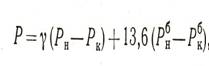
where Рн and Рк - pressure in the pipeline at the beginning and at the end
tests;
The pipeline is considered to have passed the test if no violation of its integrity is found, and the value of the pressure drop does not exceed the permissible value.
Pneumatic testing of cast iron pipelines can be carried out if the working pressure in them does not exceed 5 kgf / cm 2. At a higher working pressure, only a preliminary test is carried out pneumatically, and the final test is carried out hydraulically.
When conducting a preliminary test (before backfilling the trenches), the pressure is first increased to 1.5 kgf / cm 2 and the pipeline is kept under it for 30 minutes. Then this pressure is reduced to 1 kgf / cm 2 and the pipeline is inspected.
The final test of cast-iron pipelines by pneumatic method is carried out after backfilling of trenches in the same manner as for steel ones, but at a test pressure not exceeding 6 kgf / cm 2.
Pneumatic testing of asbestos-cement pipelines is allowed if the working pressure in them is not higher than 5 kgf / cm 2.
A preliminary test (for strength) is carried out under a test pressure equal to the working pressure plus 2 kgf / cm 2, but not exceeding 6 kgf / cm 2. First, the pressure is increased to 1.5 kgf / cm 2, after which it is reduced to 1 kgf / cm 2 and the pipeline is inspected. Defects are eliminated at atmospheric pressure in the pipeline.
The final test of asbestos-cement pipelines is carried out in the same way as for cast iron.
The pneumatic test of polyethylene pipelines is allowed only for strength, not earlier than two hours after the last welding in the test area and without odorizing the air. The final (tightness) test should only be carried out hydraulically.
A preliminary pneumatic test is carried out at a test pressure 50% higher than the working pressure, but not more than: for pipes with a nominal pressure of 6 kgf / cm 2 - 9 kgf / cm 2; for pipes with a nominal pressure of 2.5 kgf / cm 2 - 3.8 kgf / cm 2.
The pipeline is kept under test pressure for 30 minutes. Then the pressure is reduced to 3 kgf / cm 2 and the pipeline is inspected. Defects are eliminated at atmospheric pressure in the pipeline.
The pipeline is considered to have passed the test if no leakage or other defects are found on it.
To check pipelines for tightness and strength, they are carried out under pressure with water and gases.
In most cases, work is carried out hydraulically.
Pneumatic is used in cases when:
- the air temperature is below 0 degrees;
- there is no required amount of water;
- high stress is created in the pipeline or support structure;
- when tested with air or gas according to the project.
Rules of conduct, according to SNiP
When conducting hydraulic tests, the pressure is set equal (in the absence of parameters in the project):
- for pipelines made of steel working with a pressure of less than 0.5 MPa, for systems operating with a temperature of more than 400 degrees, regardless of pressure - 1.5 bar;
- for a steel pipeline with a pressure of more than 0.5 MPa - 1.25 bar, but not less than 0.8 MPa;
- for pipes of other design - 1.25 bar.
During strength tests, the pressure is maintained for 5 minutes, then reduced to working, the pipes are inspected.
The pressure for glass pipes is kept for 20 minutes.
The rest of the pipelines are tapped at the seam with a steel hammer weighing up to 1.5 kilograms, pipes made of non-ferrous metals - with a wooden weight of 800 grams.
Pipes made of other materials do not knock.
Result hydraulic test is recognized as satisfactory if no pressure drop is noticed during inspection, there is no leakage and fogging in the seams, housings, in the oil seals ().
Upon completion of the work, an act of acceptance of the pipeline into operation is compiled..
The pressure is built up to the prescribed, then the pipes are disconnected from the water supply or pressure testing device.
Checking plastic
During testing of plastic pipes(soldering video polypropylene pipes see with your own hands) the required pressure is achieved by pumping water.
If the tests are carried out in frost, then measures are taken to prevent water freezing: heating, additives,.
FACT. Large gas and oil companies develop instructions with the participation of specialized specialists based on theoretical calculations and experimental studies.
Main pipelines- sources of risk, therefore, strict requirements are imposed on the operation of such communications.
Pneumatic test carried out with air or inert gases.
Checking the strength and tightness is prohibited in working shops, on an overpass, in a channel, a tray where pipes are located.
 Gas pressure depends on the parameters of the pipelines, materials.
In general, it is equal to the hydraulic test pressure.
Calculations and formulas
Maximum length of the tested section, the limiting pressure values during pneumatic testing of an aboveground pipeline depends on the diameter of the pipes and is calculated by the formulas:
![]()
Where:
- Pmin - pressure for testing in MPa;
- Kн - coefficient of reliability from table 11 SNiP 2.05.06-85;
- n is the coefficient of reliability under loads from table 13 of SNiP 2.05.06-85;
- m - coefficient of working conditions from table 11 SNiP 2.05.06-85;
- Pwork - the maximum value of the working pressure in MPa.
The length of the area to be checked is calculated using the formula:
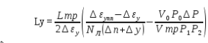
Where:
- N L - the number of sheets per pipe, two seam NL = 2, other types of NL = 1;
- Ltr - the length of the tested section, m;
- ∆P - errors in pressure addition measurements;
- ∆y - errors in volume addition measurements;
- ∆ε y is the deformation of the pipe when the pressure changes by the index P;
- P 1, P 2 - sequential pressure measurements, Pa;
- ∆εupp is the permissible deformation of pipes when the pressure rises by the index P;
- P 0 - atmospheric pressure, Pa;
- V 0 - the possible volume of air that remained in the pipeline at P 0, m3.
 Pneumatic strength test, if cast iron fittings are installed, it is carried out at a pressure of not more than 0.4 MPa.
After checking, it is forbidden to tap the water pipes (which are better for hot water supply, it is written) with a hammer until the pressure drops.
IMPORTANT!
The formulas used in the calculations, the coefficients may differ, depending on the field of application of materials, test developers.
It is necessary to use a mathematical tool developed for specific pipelines (automatic irrigation systems - read how to do it yourself).
Maximum allowable pressure
Gas test pressure raise gradually with constant inspection of the pipes: 30% of the maximum pressure, 60% of the maximum pressure and the peak value.
On examination, the increase in pressure stops.
The last inspection is carried out at operating pressure., and combine it with a leak test. Defects are detected with a soap solution or other means.
Defects of transverse seams found during testing are not corrected.
A damaged pipe section is cut out, and a new segment is replaced.
 The length of the sections between the seams should be at least 20 centimeters with a pipe diameter (which is recommended for a plumbing in an apartment written in the article) over 150 millimeters.
With a smaller diameter, the straight section should be at least 10 centimeters.
With long-term maintenance of high pressure, pipes are constantly being examined.
If the pressure has increased due to heating, then the test pressure is gradually reduced (read about the reasons for the water hammer in the pipeline) to the required level.
Requirements for the organization of the site
The tests are carried out in a fenced and secured area, regardless of whether the test is carried out indoors or outdoors.
No human access to the test site.
The minimum boundary of the protected area for aboveground tests is 25 meters, for underground ones - 10 meters.
Borders should be marked with flags and checkpoints. Posts are being installed - one post for two hundred meters of the pipeline.
In the dark provide high-quality illumination of the borders and the test area itself.
Compressors for creating test pressure are located outside the security zone. The lines from the compressors are pre-checked hydraulically.
Outcome
The detection of leaks, fogging leads to an unsatisfactory assessment of the test. The pipes are inspected by specially trained personnel. Upon completion of the tests, an act is drawn up in the prescribed form.
See how pipelines and fittings are tested at the stands of a company that produces reinforced-plastic pipes and fittings.
ENiR
§ E9-2-9. Pipeline testing
Characteristics of the working conditions
Testing of pipelines is carried out hydraulically or pneumatically.
The pipelines are tested for strength and tightness, usually hydraulically. Depending on the climatic conditions in the construction area and in the absence of water, a pneumatic test method can be used for pipelines with an internal design pressure Pр, not exceeding: underground cast iron, asbestos-cement and reinforced concrete - 0.5 MPa (5 kgf / cm2); underground steel - 1.6 MPa (16 kgf / cm2); overhead steel - 0.3 MPa (3 kgf / cm2).
Testing of pressure pipelines of all classes is carried out, as a rule, in two stages:
the first - a preliminary test for strength and tightness is performed after filling the sinuses with tamping the soil by half the vertical diameter and filling pipes in accordance with the requirements of SNiP III-8-76 "Earthworks" with butt joints left open for inspection, but before closing the channels and installation of stuffing box expansion joints, sectional valves, hydrants, plungers, safety valves;
the second - the acceptance (final) test for strength and tightness is carried out after complete filling of the pipeline and completion of construction and installation work, installation of all equipment of heating networks (valves, expansion joints, etc.), provided for by the project of backfilling the trench, but before installing hydrants, plungers, safety valves, instead of which flange plugs are installed during the test.
Preliminary testing of pipelines that are accessible for inspection in working order or subject to immediate backfilling during construction (performance of work in winter time, in cramped conditions) with appropriate justification in projects, it is allowed not to produce.
Non-pressure pipelines are tested for tightness twice: preliminary before backfilling and acceptance (final) after backfilling.
The assembled gas pipeline is tested for strength and tightness with air after installation of the shut-off valves.
Scope of work
When pneumatic testing of pipelines
1. Cleaning and purging of pipelines.
2. Installation of plugs and pressure gauge.
3. Connection to the pipeline of a compressor or an air cylinder.
4. Filling the pipeline with air to the specified pressure.
5. Preparation of a soap solution. 6. Inspection of the pipeline with smearing the joints with soapy water and marking the defective spots.
7. Elimination of detected defects.
8. Secondary testing and delivery of the pipeline.
9. Disconnect the compressor or cylinder and bleed the air from the pipeline.
10. Removing plugs and pressure gauge.
During hydraulic testing of pipelines
1. Cleaning of pipelines.
2. Installation of plugs with their fixing with temporary stops, pressure gauge and taps.
3. Connection of water supply and press.
4. Filling the pipeline with water up to the specified pressure.
5. Inspection of the pipeline with a mark of defective places.
6. Elimination of detected defects.
7. Secondary testing and delivery of the pipeline.
8. Disconnecting the water supply and draining the water from the pipeline.
9. Removing plugs, stops and pressure gauges.
When flushing pipelines
1. Connecting the water supply.
2. Filling the pipeline with water.
3. Flushing the pipeline until the water is completely cleaned of turbid impurities.
4. Drainage of water from the pipeline.
5. Filling the pipeline with chlorine water.
6. Drain the chlorine water from the pipeline.
7. Secondary filling and flushing of the pipeline after chlorination.
Table 1
| Pneumatic test | Flushing and chlorination | ||||||||
| Link composition | steel pipelines | steel, cast iron and asbestos-cement |
ceramic, reinforced concrete and concrete | steel, cast iron and asbestos-cement pipelines | |||||
| Pipe diameter, mm, up to | |||||||||
| 600 | 2000 | 600 | 2000 | 600 | 1600 | 3500 | 600 | 2000 | |
| External piping installer | |||||||||
| 6 bit | 1 | 1 | — | — | — | — | — | — | — |
| five " | — | — | 1 | 1 | 1 | 1 | 1 | — | — |
| four " | 1 | 2 | 1 | 2 | — | 1 | 2 | 1 | 1 |
| 3 " | 2 | 1 | 2 | 1 | 1 | — | — | 1 | 2 |
| 2 " | — | — | — | — | — | — | — | 2 | 1 |
table 2
Time rates and prices for 1 m of the pipeline
| Diameter | Pneumatic | Hydraulic testing of pipelines | Flushing and | |||
| pipes, mm, up to | testing of steel pipelines | steel and cast iron | asbestos-cement | ceramic, concrete and reinforced concrete | chlorination of pipelines | |
| 100 | — | 1 | ||||
| 200 | 2 | |||||
| 300 | 3 | |||||
| 400 | 4 | |||||
| 600 | 5 | |||||
| 800 | — | 6 | ||||
| 1000 | — | 7 | ||||
| 1200 | — | 8 | ||||
| 1600 | — | 9 | ||||
| 2000 | — | 10 | ||||
| 2400 | — | — | — | — | 11 | |
| 3000 | — | — | — | — | 12 | |
| 3500 | — | — | — | — | 13 | |
| but | b | in | r | d | № | |
Notes: 1. The rates of the table. 2 provides for testing steel, cast iron and asbestos-cement pipelines in sections up to 500 m, and ceramic, concrete and reinforced concrete sections up to 100 m. When testing steel, cast-iron and asbestos-cement pipelines with sections St. 500 m, and ceramic, concrete and reinforced concrete plots of St. 100 m Time Rates and Prices multiply by 0.75 (PR-1).
2. When testing pipelines by various sections of workers for preliminary testing, the Time Standards and Prices shall be multiplied by 0.6 (PR-2), for the final test by 0.4 (PR-3).
3. During hydraulic testing of pipelines from a hand-held press, the Time Standards and Prices shall be multiplied by 1.2 (PR-4).
4. The laying of a temporary water supply system should be normalized according to § E9-1-2, Table 2, Note 1.
5. When flushing pipelines without chlorination, the Time Standards and Prices of the column "d" should be multiplied: with double filling of the pipeline - by 0.6 (PR-5), with a single filling - by 0.4 (PR-6).
For pneumatic testing, the pressure inside gas pipelines, oil and oil product pipelines is created with air or natural gas. As sources of compressed air, mobile compressor units are used, which, depending on the volume of the cavity of the test area and the magnitude of the test pressure, are used one at a time or combined into groups. The time for filling the pipeline with air can be determined from the nomogram of the recommended app. 1. Natural gas for testing pipelines should be supplied from a well (for field pipelines only) or from existing gas pipelines crossing or directly adjacent to the construction site. The pressure during pneumatic strength test of the pipeline as a whole at the last stage should be equal to 1.1 R slave, and the duration of holding under this pressure is 12 hours. The graph of pressure changes in the pipeline during pneumatic testing is shown in Fig. 11. Filling the pipeline with air or natural gas is carried out with inspection of the route at a pressure equal to 0.3 of the strength test, but not higher than 2 MPa (20 kgf / cm 2). During pumping, an odorant should be added to natural gas or air to facilitate subsequent pipeline leak detection. To do this, it is necessary to install installations for dosing odorant at the nodes of connection to gas or air sources. The recommended rate of odorization with ethyl mercaptan is 50-80 g per 1000 m 3 of gas or air. If a leak is found during inspection of the route or in the process of raising the pressure, the supply of air or gas to the pipeline should be stopped immediately, after which the possibility and expediency of further testing or the need to bypass air or gas to an adjacent section should be established.
Fig. 11. Graph of pressure change in the pipeline during pneumatic test:
1 - pressure rise; 2 - pipeline inspection; 3 - test of endurance; 4 - pressure relief; 5 - check for tightness.
Inspection of the route with an increase in pressure from 0.3 R isp before R isp and the duration of the strength test is prohibited. After the end of the pipeline strength test, the phenomenon must be reduced to the design worker and only after that a control inspection of the route should be performed to check for leaks. When depressurizing, air or gas should be bypassed to adjacent areas if possible. Considering that, during pneumatic testing, the processes of filling the pipeline with natural gas and air up to the test pressure take a long time, it is necessary to pay special attention to the rational use of the energy accumulated in the pipeline by repeated bypassing and pumping natural gas or air and. tested areas to areas to be tested. To prevent gas or air losses in case of ruptures, filling the pipeline with a pressure medium and raising the pressure to the test pressure must be carried out along the bypass lines with closed linear valves.
Pneumatic testing of pipelines can be carried out at the discretion of the construction organization in case of difficulties during the hydraulic test (lack of water in the construction area, winter time, etc.).
When pneumatic testing of pipelines, the test pressure should be set in the project and indicated in the working documentation. In the absence of a test pressure value in the working documentation, it should be taken:
for steel pipelines with a design internal pressure pP of 0.5 MPa inclusive, equal to 0.6 MPa for both preliminary and acceptance test;
for steel pipelines with a design internal pressure pp FROM 0.5 to 1.6 MPa inclusive, equal to 1.15 pp for both preliminary and acceptance tests;
for cast iron, reinforced concrete (with a steel core and vibrohydropressed) and asbestos-cement pipelines, regardless of the value of the design internal pressure, equal to 0.15 MPa for preliminary and 0.6 MPa for acceptance testing.
When conducting preliminary and acceptance tests for strength, the pipeline should be kept under test pressure for 30 minutes. Air must be pumped to maintain the test pressure.
Defects identified and noted during inspection of the pipeline should be eliminated after reducing the excess pressure in the pipeline to zero (to atmospheric pressure). After elimination of defects, the pipeline must be retested.
The pipeline is recognized as having passed the preliminary and acceptance pneumatic strength tests, if a thorough inspection does not reveal any violations of the integrity of the pipeline, defects in butt and welded joints.
The assessment of the tightness of pipelines made of different materials during the acceptance test is carried out at a pressure of 0.03 MPa. The pressure drop is observed according to the indication of the liquid pressure gauge, connected for this in parallel with the spring technical pressure gauge
When determining the pressure drop during the test period, the change in barometric pressure, determined from an aneroid barometer or from a local meteorological station, should be taken into account.
The true value of the pressure drop in the pipeline p prn conducting a pipeline leak test should be determined by the formula
The pipeline is recognized as having passed the pneumatic final test, if it is not violated. In this case, the formation of air bubbles on the outer wetted surface of reinforced concrete vibrohydropressed pipes is allowed
If the true value of the pressure drop in the pipeline exceeds the permissible value, then the pipeline is recognized as having passed the pneumatic test and measures must be taken to detect and eliminate hidden pipeline defects. Then a re-pneumatic pipeline test should be performed.
In cases where it is difficult to carry out a preliminary test by a hydraulic method, and during the acceptance test by a pneumatic method, over-. underlying assessment of the quality of the pipeline, in agreement with the design organization, it is allowed to test pipelines in a mixed way: preliminary - pneumatic and final - hydraulic methods.
At test pressures of more than 0.1 MPa, one should use spring-loaded technical manometers certified in accordance with the established procedure in accordance with GOST 8625-77E of an accuracy class of at least 1.5 (mainly accuracy classes 0.6 and 1).
When measuring differential pressure, use a single-tube liquid pressure gauge, the working fluid in which can be water at positive outside temperatures and kerosene at negative temperatures.
The following requirements are imposed on a one-pipe liquid pressure gauge:
the open glass tube of the manometer must be at least 1 m long and with an outer diameter of 8-14 mm;
the scale on which the pressure drop is read should have millimeter divisions;
the hose connecting the air-liquid tank with the glass tube must have a length of no more than 4 m and an inner diameter of 7-13 mm (1 mm less than the outer diameter of the glass tube);
the inner diameter of the tank must be at least 100 mm, the volume must be at least 2 liters;
at a tank height of more than 300 mm, a water gauge glass and a reading are installed on it. A2 is taken from the liquid level in the tank;
if the tank height is less than 300 mm, the gauge glass may not be installed and A2 is counted from the middle of the tank height;
the hose connecting the tank to the glass tube must be routed upright to prevent air pockets from forming in it.
For testing pipelines, it is recommended to use inventory end caps, one of which is used to connect to the compressor and connect a one-pipe liquid pressure gauge, the other to connect a spring pressure gauge.
Leak detectors GTI-2T6, GTI-3, GTI-5, etc. can be used as special devices (halogen leak detectors).
Test preparation
Before the pneumatic tests(preliminary and acceptance) on the tested section of the pipeline must be:
all works on sealing butt joints, installation of stops, installation of fittings and fittings have been completed; satisfactory results of quality control of welding and insulation of steel pipelines were obtained;
steel flange plugs were installed instead of hydrants, plungers, safety and anti-vacuum valves at the ends of the tested sections and at the points of connection to the operated pipelines;
all valves installed on its linear part are open;
temporary stops are installed at the points of butt joints, where longitudinal displacements can occur during pipe testing;
means for filling the pipeline with air were prepared, temporary communications were installed; installed devices and taps necessary for testing; the correctness of the connection to the compressor pipeline has been checked;
wells were drained and ventilated, into which technical personnel will be lowered to inspect the pipeline nodes installed in them;
the responsible executor received a work permit for the performance of work of increased danger in the manner and in the form established by the requirements of SNiP Sh-4-80;
the sufficiency of the actual holding time of the pipeline to equalize the temperature of the air in the pipeline with the temperature of the soil was checked according to the entries in the work log;
organized shifts at the boundaries of the section of the security zone.
The line supplying air from a mobile compressor or from a compressed air line must have: at least two shut-off devices: a moisture-oil separator equipped with a valve for moisture (condensate) and oil release and a safety valve (if it is absent in a mobile compressor unit); a pressure gauge with a transition cock and a branch pipe for connecting a control pressure gauge.
In order to avoid the influence of vibration during compressor operation on the readings of spring technical pressure gauges, their connection to the test section of the pipeline should be made through the expansion pipe
Defect detection methods
Leaks and other defects in the test section of the pipeline can be detected in the following ways:
by the sound of leaking air;
by bubbles formed in places where air leaks from the pipeline when butt joints and other places are covered with soap emulsion;
by the smell of odorized air flowing out through leaks in the tested section of the pipeline;
according to the indications of halogen leak detectors when using halogen additives to the air introduced into the tested pipeline.
When preparing a soap emulsion for coating joints and possible places of leaks, soap (powder) is dissolved in water at the rate of 35 g of soap powder per 1 liter of water. To prevent the soap emulsion from drying out quickly, a few drops of glycerin are added to it. At subzero air temperatures, a larger amount of glycerin (or ethyl alcohol) should be added to the soap emulsion to prevent it from freezing.
When determining the places of leaks in the tested section of the pipeline using odorized air, ammonia, ethyl mercaptan, pentalaram and other gases with a pungent odor can be used as an odorant. These odorants are added to the air sucked in by the compressor and fed into the pipeline through the Wolfe vessel.
Ammonia (25% strong ammonia solution) should be introduced into the pipeline at the beginning of the test at an air pressure of about 0.03 MPa. The test area is also inspected to places where leaks are possible (butt joints, fittings connections, etc.), bring a cord or swab soaked in hydrochloric acid, or a glass rod soaked in this acid. A cloud should appear over the defective spot white... A colorless solution of phenolphthalein can also be used to locate defective spots, wetting butt joints and other places of possible leaks with it. A solution of phenolphthalein, when interacting with ammonia, becomes bright crimson.
When determining the places of air leaks using halogen leak detectors, carbon tetrachloride, chlorophones, iodiforin, freon, etc. can be used as halogens.
The places of defects found on the tested section of the pipeline are marked with chalk or paint, and information about the nature of the defect and its location is entered into the defective test sheet.
We advise you to read
 Sale of the only housing for debts that was allowed by the Supreme Court of the Russian Federation Foreclosure on the only housing of the Armed Forces of the Russian Federation
 WWII monuments: production and restoration
 WWII monuments in our travels
 Hanseatic League: a defunct empire Creation of a Hanseatic merchant union objects that