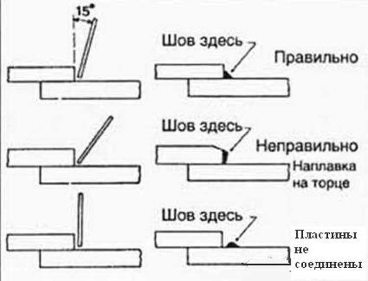
The quality of the welded joint depends on the type of seam selected, the electrode and the operating mode of the apparatus. For this, it is recommended to be guided by current standards, and in particular - GOST 5264-80. It details the features and types. welded joints and types of welds. According to GOST, special requirements are made for the performance of work.
Butt
The most popular type of connection, as it is characterized by a minimum metal voltage, ease of execution and reliability. Depending on the thickness of the welded edge, it can be cut at a right or oblique angle. The use of a one-sided bevel is also acceptable.
Advantages of butt welds:
- minimum rate of consumption of the main and weld metal;
- optimal welding time;
- good quality connections.
The latter is achieved only by observing the technology. The bevel angle can vary from 45 ° to 60 °. It depends on the thickness of the metal. Similar geometry is applicable for sheets from 20 mm and more. Material characteristics are also taken into account.
Overlap
The formation of the compound by the method of applying sheets to each other is relevant for the thickness of the metal in the range from 8-12 mm. In this case, unlike butt welding, there is no need to process the surface - it is enough to evenly cut the workpiece. It is important to correctly calculate the size of the overlap.
Features of lap weld:
- increased consumption of the main and deposited material;
- a seam is formed between the surface of one sheet and the end face of another;
- scope - spot, roller and contact welding.
Before starting work, the sheets must be aligned to ensure a tight hold.
Tauris
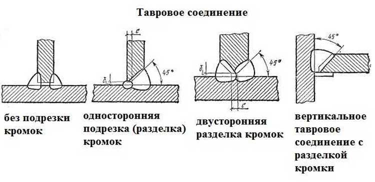
This is a T-joint, in which the end of one of the sheets is welded to the plane of the other. For reliability, the first one can make one or two-sided bevels. With their help, the volume of deposited metal increases. Scope - metal structures of complex shape.
Before starting work, you need to consider the following factors:
The bevel configuration is standard, the angle depends on the thickness of the metal.
Corner
They are used to connect two structural elements at a certain angle. Unlike T-joints, the presence of a gap is unacceptable. Reliability is provided by bevels and a large amount of directional metal.
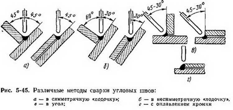
Specificity of fillet welds:
- surface preparation is necessary - the formation of bevels of a simple or complex configuration;
- for thin-walled workpieces one-way connection is allowed;
- geometry taken into account weld.
A similar method is most often used for the manufacture of tanks or similar in design.
Auxiliary welds
In addition to the above-described main methods of joining steel elements, GOST provides auxiliary ones. They can be used to form a reliable joint, taking into account the required operational qualities of the product.
Depending on the specifics of the weld, the following methods for forming a welded joint are used:
- Slotted. Necessary to achieve maximum reliability. In one of the materials, a recess is made to install another sheet.
- Face. Belong to the category of lateral. Sheets are superimposed on each other, seams are made at the ends of the structure.
- With overlays. Recommended for structures with complex surface configuration. A special pad is used to ensure the connection of the two components.
- With electro rivets. The bonding process is similar to traditional riveting. The difference is that the hole is filled with weld metal.
The choice of a particular weld depends on the end result - the reliability and durability of the connection.
Welds are heterogeneous in their structure and include the following zones: the zone of the base metal, weld, fusion and thermal influence.
The following types of welding connections are distinguished:
1) Butt.
This is the most common type of connection for various welding methods, which has several advantages compared to others: high welding performance, minimizing the consumption of welded and deposited metal, high strength with proper observance of welding technology, and the absence of own structural stresses. Moreover, such joints require careful preparation of the edges and accuracy of the relative positioning of the edges of the parts during assembly for welding.
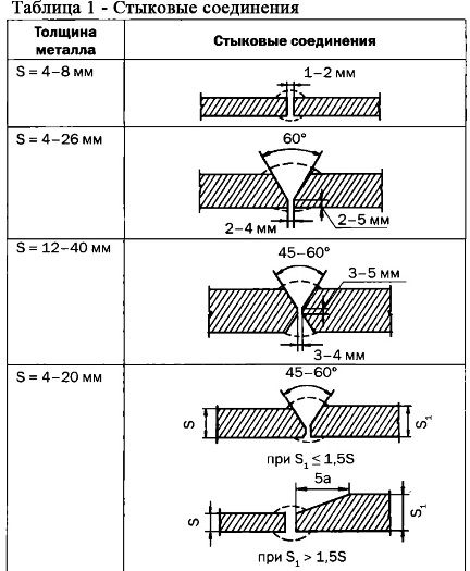
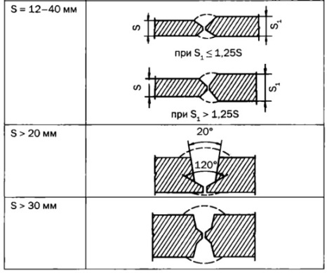
Edging of edges can be different, its examples are shown in table 1.
With a large thickness of the edges, a cup-shaped groove is used, for a thickness of 20 ... 50 mm - one-sided, over 50 mm - two-sided. Butt joints are widely used in welding sheets, pipes, high-quality metal.
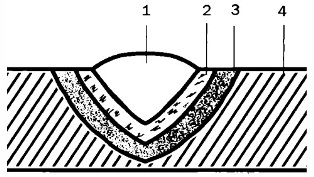
Fig. 1. Weld zones: 1 - weld, 2 - fusion zone, 3 - heat-affected zone, 4 - base metal zone
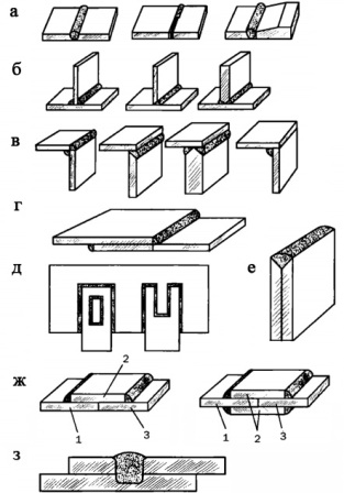
Fig. 2. Types of welded joints: a - butt, b - T-joint, c - angular, g - lap joint, d - grooved, g - with overlays, s - with electro-rivets, 1 ... 3 - base metal, 2 - overlay, 3 - electric rivets
2) Corner.
Examples of corner joints are shown in fig. 2, c. They can be single or double sided to increase strength. They are also used for welding sheet, shaped and pipe blanks. The angle of inclination of the workpieces can be different, preliminary cutting of the edges is required.
3) Tauri.
The vertical element of the T-joint should have a cutting edge. It is recommended to make a bevel on both sides, if it is impossible to penetrate it, only on one side. In this case, a gap must be provided between the vertical and horizontal parts for boiling over the entire thickness of the sheet. Taurus is used to connect sheet blanks.
4) Lap top.
Such compounds are mainly used in spot and resistance welding, since in other cases the consumption of the base and electrode metal unreasonably increases. In the case of lap joint, the cutting of the edges at an angle is not required, but they must be trimmed. To avoid corrosion between sheets, it is recommended to weld the joint on both sides.
5) Face.
In this embodiment, the sheets are laid on top of each other in the form of a “sandwich” and welded at common ends.
6) Slotted.
They are used when it is necessary to strengthen the lap joint. The slot is made in an open or closed version.
7) With overlays.
Such compounds are also used as an option for reinforcing butt or lap joints. An example is the use of reinforcing rings on the inner surface during assembly-welding of tank shells.
8) With electric rivets.
1. Steel welding technology
Preparation of structures for welding
Preparation of structures for welding is divided into three stages:
1. processing edges to be welded;
2. assembly of structural elements for welding;
3. Additional cleaning, if required, of welded joints.
Edging of structures to be welded is carried out in accordance with the drawings of structures and in accordance with the requirements of GOST 5264–80 and other GOSTs for the main types and structural elements of welded joints. The edges of the joints for welding are processed on edge-cutting or milling machines, as well as by oxygen and plasma cutting on special machines. The dimensions of the edge elements must comply with the requirements of GOST.
An important step in preparing the design for welding is assembly for welding. For manual arc welding, structures are assembled using assembly devices or tacks. The composition of the assembly fixtures: clamps 1 perform a variety of operations for assembling angular metal, beams, strips, etc .; wedges 2 are used to assemble sheet structures; levers 3 - for the assembly of angular metal and other structures; coupling angles 4 and angular clamps 8 - for the assembly of sheet structures; jacks 5 - for tightening shells, beams and other structures; gaskets with wedges 7 - for the assembly of sheet structures in compliance with the gap; tie rods 10 and squares. And - for the assembly of sheet structures for welding without tacks. Other types of devices are also used.
Before assembly, the processed structural elements must be measured, their edges inspected, as well as the metal adjacent to them, thoroughly cleaned of rust, oil, paint, dirt, ice, snow, moisture and scale. In workshop conditions, structural elements are assembled on shelves - slabs having grooves for installing devices (bolts, couplers, pins, etc.) that fasten the assembled elements to the sizes provided for in the drawings. The simplest racks of horizontal beams mounted on racks 200–400 mm high are also used. 13.3 shows an example of assembly of sheet structures using the simplest devices and assembly of structures from profile metal - angular, I-beam, etc. Edges of assembled structures to be welded must conform to drawings and standards in their shape and dimensions.
The joints of structures during assembly are fixed with tacks - short welds to fix the relative position of the parts to be welded. Tack welds should be placed at weld locations, with the exception of their intersections. Tack lengths for steels with a yield strength of up to 390 MPa should be at least 50 mm and the distance between them should be no more than 500 m, for steels with a yield strength of more than 390 MPa, tacks should be 100 mm long and the distance between them is not more than 400 mm. With a small thickness of the assembled parts (4–6 mm), tacks can be shorter (20–30 mm) and the distance between them is 200–300 mm. When assembling tacky bulky heavy structures canted during welding, the location of the tacks and their value are indicated in the welding work design. The tack welds that are removed during welding should be performed by welders who will subsequently weld the stuck joints.
Tacking gives rigidity to the structure and prevents the movement of parts from shrinkage during welding, which can lead to the formation of cracks, especially in elements of large thickness. Therefore, assembly on tacks is used for metal thicknesses of 6–10 mm, and for larger thicknesses, assembly devices are used that fix the shape and dimensions of structures, but allow it to move slightly from welding shrinkage. These devices are wedge ties (see 13.1).
Immediately before welding, the assembled joints are subject to mandatory inspection and, if necessary, additional correction of assembly defects and cleaning.
When welding in a vertical position, the current decreases by 10–20%, when welding horizontal seams - by 15–20% and when welding ceiling seams –– by 20–25%.
The type of current and polarity are determined depending on the electrodes accepted for welding, for example, alternating or direct current can be used for MP-3 electrodes, only direct current for UONII-13/45 electrodes reverse polarity etc.
The welding speed (arc movement) largely depends on the qualification of the welder and his ability to conduct the welding process with interruptions only for changing the electrode. In addition, the welding coefficient of the applied electrodes and the strength of the welding current influence the welding speed. The greater the deposit coefficient and current strength, the faster the arc moves and, consequently, the welding speed increases. It should be borne in mind that an arbitrary increase in the current strength can cause overheating of the electrode.
Coefficient / C, determined by the table. 13.1, depends on the type of coating of the electrodes. For example, for electrodes with an acidic or rutile coating, the maximum value of the coefficient with a diameter of 3-4 mm is K \u003d 45; for electrodes with a basic coating with a diameter of 3-4 mm D "\u003d 40; with a cellulose coating of the same diameter / (\u003d 30.
Based on the formula for the linear energy of welding qn (Ch. 3), an approximate dependence of the linear energy on the cross-sectional area of \u200b\u200bthe weld bead, J / mm
where Qo is a coefficient depending on the type of electrodes or wire used in mechanized welding methods; Fm–\u003e roller cross-sectional area, mm2.
For electrodes of the UONII-13/45 and SM-11 grades, the value of Qo \u003d 65 J / mm3. Thus, knowing the linear energy, it is easy to determine the cross section of the weld bead and vice versa.
2. Types of welded joints. Welds
Terms and definitions of basic concepts for metal welding are established by GOST 2601–84. Welded joints are divided into several types, determined by the mutual arrangement of the parts to be welded. The main ones are butt, corner, tee, lap and butt joints. To form these joints and ensure the required quality, the edges of structural elements joined by welding must be prepared in advance. Forms of edge preparation for manual arc welding of steel and alloys on an iron-nickel and nickel basis are established by GOST 5264–80.
Butt joint called the connection of two elements adjacent to each other by end surfaces.
GOST 5264–80 provides for 32 types butt joints, conventionally designated Cl, C2, C28, etc., having different edge preparation depending on the thickness, location of the elements to be welded, welding technology and the availability of equipment for processing edges. With a large thickness of the metal by manual welding, it is impossible to melt the edges to the entire thickness, therefore, the edges are cut, i.e. bevel them on two or one side. The edges are mowed on a planing machine or thermally sharp (plasma, gas-oxygen). The total angle of the bevel (50 ± 4) °, this preparation is called one-sided with a bevel of two edges. In this case, the amount of blunting (not slanted part) and the gap must be maintained, the values \u200b\u200bof which are set by the standard depending on the thickness of the metal. Butt joint seam called butt seam, and the weld seam is a smaller part of the bilateral seam, performed previously to prevent burn-throughs during the next welding of the main seam, or applied last, after its completion.
When preparing the edges of steel with a thickness of 8–120 mm. Both edges of the welded elements are chamfered on both sides at an angle of (25 ± 2) ° each, while the total bevel angle is (50 ± 4) °, blunting and clearance are set by the standard depending on the thickness of the steel. This preparation is called double-sided with a bevel of two edges. With this preparation, the processing of edges is complicated, but on the other hand, the volume of deposited metal sharply decreases in comparison with one-sided preparation. The standard provides for several options for bilateral edge preparation: preparation of only one upper edge, used in the vertical arrangement of parts, preparation with uneven ps thickness, bevel edges, etc.
Corner connection called the connection of two elements located at an angle and welded at the junction of their edges. There are 10 such compounds: from U1 to U10.
For a metal thickness of 3-60 mm, the edge of the adjacent element is beveled at an angle of (45 ± 2) 1 °, the weld is the main and sub-warp. With the same thickness and through penetration, you can do without a weld seam. Often, an angular connection is used with a steel lining, which provides reliable penetration of elements throughout the cross section. With a metal thickness of 8–100 mm, two-sided cutting of the adjacent element is used at an angle of (45 ± 2) °.
T-joint A welded joint is called in which the end face of one element abuts at an angle and is welded with fillet welds to the side surface of another element. The standard provides for several types of such compounds: from T1 to T9. A common compound is for a metal 2–40 mm thick. For such a connection, no beveling of the edges is made, but they provide even trimming of the adjacent element and the even surface of the other element.
With a metal thickness of 3-60 mm and the need for a continuous seam between the elements, which is provided for by the design project, the edges are cut in the adjacent element at an angle of (45 ± 2) °. In practice, a T-joint with a lining is often used with a steel thickness of 8–30 mm, as well as a joint with a two-sided bevel of the edges of the adjacent element with a steel thickness of 8–40 mm. All these connections with bevelled edges of the adjacent element provide a continuous weld and the best working conditions of structures
Lap joint A welded joint is called in which the elements welded by fillet welds are parallel and partially overlap each other. The standard provides for two such compounds: HI and H2. Varieties of lap joints are sometimes used: with a patch and with point seams connecting parts of structural elements.
Of these welded joints, the most reliable and economical are butt joints, in which current loads and efforts are perceived in the same way as in whole elements that have not undergone welding, i.e. they are almost equivalent to the base metal, of course, with the appropriate quality of welding work. However, it should be borne in mind that the processing of the edges of the butt joints and their fitting for welding is quite complicated, in addition, their use can be limited by the features of the shape of the structures. Corner and tee joints are also common in designs. Lap joints are the easiest to use, since they do not need preliminary cutting of the edges, and preparing them for welding is simpler than butt and corner joints. As a result of this, and also because of the structural form of some structures, they have become widespread for joining elements of small thickness, but are allowed for elements up to 60 mm thick. The disadvantage of lap joints is their inefficiency caused by overspending of the base and deposited metal. In addition, due to the displacement of the line of action of the forces when moving from one part to another and the occurrence of stress concentration, the bearing capacity of such compounds decreases.
In addition to the listed welded joints and seams, manual arc welding uses joints at sharp and obtuse angles according to GOST 11534–75, but they are much less common. For shielding gas welding, welding of aluminum, copper, other non-ferrous metals and their alloys, welded joints and seams are used, provided for by individual standards. For example, the form for preparing the edges and seams of pipeline structures is provided for by GOST 16037–80, which defines the main dimensions of the seams for various types of welding.
3. Welding fittings of various classes
Currently, in construction, a large amount of welding work falls on the reinforcement of reinforced concrete. Welding is used in the manufacture of welded reinforcing products, embedded parts and installation of prefabricated reinforced concrete structures (table. 2).
table 2
| Welding method and its characteristics | Appointment | Position of the rods during welding | Type of welding |
|
submerged arc without filler metal, automatic and semi-automatic |
Production of embedded parts: lap joint of rods with flat elements | Static and dynamic | |
| T-joint of rods with flat elements | Vertical | ||
| Semi-automatic submerged bath in inventory forms | Butt joints of releases of single reinforcement rods at the interfaces between reinforcing products and prefabricated reinforced concrete structures | Horizontal vertical | Static, dynamic and repetitive |
| Single electrode bath in inventory forms with smooth inner surface, manual | Horizontal | ||
| Single electrode bathtub with steel grooved lining, manual | Horizontal | ||
| Single-electrode bath-suture with steel grooved overlay, manual open arc bare alloy wire, multi-layer seams with steel grooved overlay, semi-automatic | Horizontal vertical | ||
| Single electrode multi-layer seams with or without steel grooved lining, manual | Vertical | Static and dynamic | |
| Long seams | Horizontal | ||
| Multi-electrode bath in inventory forms with a recess for the formation of reinforcement of the seam | Horizontal | Static, dynamic and repetitive Static and dynamic |
The main types of welding during installation of reinforcing products and prefabricated reinforced concrete structures are manual arc and semi-automatic welding with coated electrodes or welding wire, respectively. For reinforcing reinforced concrete structures, hot-rolled steel according to GOST 5781–75 *, round, smooth and periodic profile, which is divided into 5 classes depending on mechanical properties, is used: A-I, A-II, A-III, A-IV, A- V (table. 3).
Table 3
| Reinforcement class | Welding methods | |
| lingering seams | multi-layer seams, multi-electrode bath, single-electrode bath | |
| A-i | E42A-F - UONI 13/45, SM-11, UP2 / 45, E42-T - ANO-5, ANO-6, ANO-1, E46-T - ANO-3, ANO-4, MP-1.MR -3, OZS-3, OZS-4, OZS-6, ZRS-2 | E42A-F - UONI 13/45, SI-11, UP-2/45 |
| A-II | E42A-F - UONI 13/45, SM-11.UP 2/45, OZS-2, E42T - ANO-5, ANO-6, ANO-1, E46T-ANO-3, ANO-4, MP-1, MR-3, OZS-3, OZS-4, OZS-6, ZRS-2 | E42A-F - UONI 13/45, SM-11, UP2 / 45, OZS-2, E50A-F - UONI 13/55, DSK-50, UP 2/55, K-5A, E55-F - UONI 13 / 55U |
| A-iii | E42A-F - UONI 13/45, SM-11, UP2 / 45, OZS-2 E50A-F - UONI 13/55, DSK-50, UP 2/55, K-5A E55-F - UONI 13 / 55U | E50A-F - UONI 13/55, DSK-50, UP 2/55, K-5A, E55-F - UONI 13 / 55U |
Notes:
1. The brands of welding wire are indicated in the order preferred for use.
2. The diameter of the solid wire is 2–2.5 mm, cored wire is 2-3 mm.
3. An asterisk marks the brand of welding wire used only when welding fittings of class A-II grade 10GT.
Reinforcing steel bars of class A-1 should be produced round smooth; rods of classes A-II, A-III, A-IV and A-V of a periodic profile. Each class of reinforcing steel must comply with GOST 5781–75 *.
4. Technological features that must be considered when welding fittings and embedded parts
Welding reinforced concrete reinforcement rods in installation conditions
In reinforced concrete structures, the connection of reinforcement rods is carried out, as a rule, by one of the electric arc welding methods or semi-automatic, namely:
- without steel brackets;
- on steel brackets;
- with round overlays or with an overlap;
- in inventory forms (copper or graphite);
- lap or tee with flat elements.
Before assembling the conjugate assemblies of the reinforcing rods, make sure that the steel classes, sizes and relative positions of the connected elements are in accordance with the design and in accordance with GOST 10922–92 of the assembled joints for welding.
The outlets of the rods, embedded products and fittings should be cleaned to clean metal on both sides of the edges or cutting 20 mm from dirt, rust and other contaminants. Water, including condensation water, snow or ice should be removed from the surface of the reinforcement rods, embedded parts and connecting parts by heating them with a flame of gas burners or blowtorches to a temperature not exceeding 100 ° C.
With increased, compared with the required, gaps between the joined rods, it is allowed to use one insert, which should be made of reinforcement of the same class and diameter as the joined rods. When butt welding with overlays, an increase in the clearance should be compensated by a corresponding increase in the length of the overlays.
The length of each release of reinforcement from the concrete body must be at least 150 mm with normal clearances between the ends of the rods and 100 mm when using the insert. We should strive to manufacture products so that the length of the outlets allows assembly and welding without inserts, i.e. adjust the clearance between the outlets at the installation site using gas cutting.
Prefabricated reinforced concrete structures mounted only at the outlets should be assembled in conductors ensuring the design position. Welding rods of reinforced concrete structures held by a crane is not allowed.
Prefabricated reinforced concrete structures with embedded parts should be assembled at tacks. Tacking should be placed at the subsequent weld seams. Tack lengths should be 15–20 mm and height (leg) 4–6 mm. The number of tacks should be at least two. Tacking should be done using the same materials and the same quality as the materials for the main seams. Before welding the main seams, the surface of the tack and adjacent sections must be cleaned of slag and metal spray. Tack welders should be carried out by trained welders with certificates for the right to carry out these works.
Burns and melting from arc welding on the surface of working rods are not allowed. Burns should be cleaned with an abrasive wheel to a depth of at least 0.5 mm. In this case, the reduction in the cross-sectional area of \u200b\u200bthe rod (recesses in the base metal) should not exceed 3%. The place of mechanical stripping should have smooth transitions to the body of the rod, and the risks from abrasive treatment should be directed along the rod. Cutting the ends of the rods with an electric arc when assembling structures or cutting the edges of the rods is not allowed. The indicated operations should be performed with special electrodes for cutting reinforcement of the OZR-2 brand.
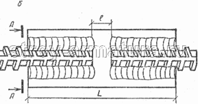
Manual arc welding of reinforcement with long seams
Manual arc welding of reinforcement is used for joining vertical and horizontal bars. The weld may be lapped and with overlays. Lap joint is performed, as a rule, by extended seams, but arc points can also be applied. In addition, it is possible to connect reinforcing bars with a long and short overlap, as well as with a unilateral or bilateral seam (Fig. 1).
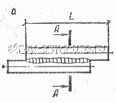

Fig. 1. Lap welded joint of reinforcement with extended seam - with a long lap in one-sided seam; b - with a short overlap and bilateral seams
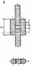
The welded joints of the reinforcement of the rods with overlays, round or corner, can be long and short. In this case, the pads can be shifted in length. Arc welding of reinforcement is performed by flank seams: two unilateral, two bilateral, four bilateral, unilateral with a “mustache” (Fig. 2). When welding reinforcement with double-sided welds, when a second weld is applied from the back of the joint, longitudinal hot cracks may occur in it. To prevent the occurrence of this type of crack, a careful selection of the type of electrodes and strict adherence to the technological mode of arc welding are necessary. Depending on the diameter of the joined rods, extended welds can be single-pass and multi-pass. The current for arc welding is selected depending on the type of electrodes. At the same time, when welding reinforcing bars in an upright position, the current should be 10–20% less than for horizontal bars.
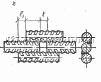
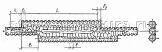
Manual arc welding of reinforcement with multilayer seams without additional technological elements
With small amounts of work and the availability of highly qualified welders, arc welding of reinforcement with multilayer seams without forming elements is possible. In this way, it is recommended to conduct arc welding of butt joints of reinforcing bars in the vertical position of the following classes of reinforcing steel: A-1 (Ø 20 - 40 mm), A-2 (Ø 20–80 mm), A-3 (Ø 20–40 mm). The structural shapes of the ends of the reinforcing bars during their joining are shown in Fig. 3. Cutting forms, bevel angles and their direction, blunting and their sizes, the gaps between the ends of the rods are standardized.
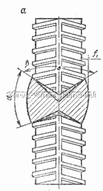
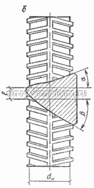
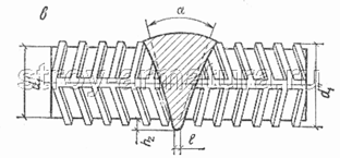
Fig. 3. Butt welded fittings made without additional elements
a - vertical single-row coaxial rods with free access from two sides to the place of welding; b-the same, with the availability of the connection on the one hand; in-horizontal coaxial rods with cutting ends
Arc welding of reinforcement is performed by a single electrode. The weld is first applied on one side of the groove, then on the other to its entire width. In the process of fusion cutting, the deposited metal is periodically cleaned of slag. The mode of electric arc welding is set in accordance with the passport data of the electrodes. Typically, electrodes with a calcium fluoride coating such as E55 or E50A are used for this type of electric welding.
Manual arc welding of reinforcement with forced seam formation
In some cases, the project requires welds of cross joints of reinforcement with forced formation of a seam. For such reinforcing products, it is recommended to use rods with a diameter of 14–40 mm from steel of classes A-1, A-2, A-3. Preliminarily, the rods are assembled in conductors, ensuring their tight contact with each other, or the fixation of the rods is achieved using tacks by welding. In this case, conductors and tacks should not impede the installation of forming elements.
Manual spot welding with two tack welds
In the conditions of a construction site, in the construction of monolithic reinforced concrete structures of buildings and engineering structures, mesh and frames made locally are widely used as reinforcing products. In such products, there are many different cross joints, welding of which is carried out using manual arc welding with dots.
The limited use of most grades of steel of classes A-2 and A-3 is due to the fact that during spot welding in the contact of the cross connection of the rods, heat is quickly removed from the deposited metal, which leads to local hardening of the steel and, consequently, to increase its brittleness. Medium carbon and low carbon reinforcing steels are particularly sensitive to these thermal effects.
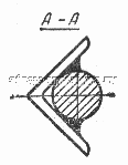
Bathroom semi-automatic submerged arc welding
Welding of fittings using the technique of bathroom semi-automatic welding of horizontal reinforcing bars is carried out using additional technological elements: demountable forms or removable linings (steel, copper, graphite). The most favorable conditions for the crystallization of the weld metal are created in copper and graphite forming devices, which makes it possible to obtain weld metal with high mechanical properties.
Forming devices are installed symmetrically to the gap between the ends of the joined reinforcing rods (Fig. 4). At a distance of 40-50 mm from the vertical axis of the joint, 2-3 turns of string asbestos are applied to the rods for a tight fit of the reinforcement to the mold. Then 20-30 g of flux are poured into the melting space. If copper molds are used, then prior to their installation, the flux is poured onto the bottom of the mold with a layer of 5–7 mm. This measure allows you to strengthen the weld at the bottom of the joint.
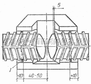
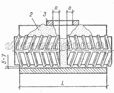
Fig. 4. Installation of demountable molds and a copper lining on the welded rods in the bathroom welding of fittings
1 - hole asbestos; 2 - flux; 3 - centering frame - a pointer to the boundaries of the melting space
Excite welding arctouching the end of the wire to the bottom edge of the end face of the reinforcing bar. Melting of the lower part of the rod end occurs during oscillatory movements of the wire across the axis of the rods for 5–15 s. Then, a similar penetration operation is performed with the second rod. Schemes for moving the end of the electrode wire during welding of the reinforcement when filling the bath with liquid metal are shown in Fig. 5. When welding fittings with a diameter of 45 mm or more, it is possible to use an additive in the form of metal grits, sawdust, chopped wire in an amount of 25–35% of the volume of the weld metal. To maintain the optimum depth of the slag bath (15–20 mm), flux is periodically added in portions.
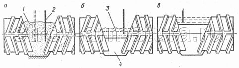
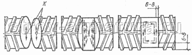
Fig. 5. Schemes for moving the end of the electrode wire (shown by arrows) during semi-automatic bathtub welding of horizontal reinforcing rods (the shape is not conventionally indicated)
a - in the initial period of penetration of the lower edges of the ends of the rods (k is the point of contact with the electrode wire of the ends of the rods to excite the arc); b - in the process of filling the cutting rods; c-at the final stage 1 - flux; 2 - electrode wire; 3 - slag bath; 4 - weld metal.
Arc welding of butt joints of vertical rods under flux, as a rule, is performed in removable copper or graphite forms. After arc excitation, the end of the electrode wire is moved by oscillatory movements according to the scheme shown in Fig. 6. After complete penetration of the end of the lower rod, in order to avoid undercutting of the upper rod, the voltage is regulated during electric welding, removing it in steps by 15–25% (2–4 times). The mode of bathroom arc welding of butt joints of vertical bars is similar to welding of horizontal reinforcing bars.
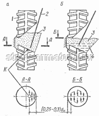
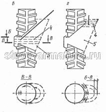
Fig. 6. Schemes for moving the end of the electrode wire during semi-automatic bath welding of rods with a bevel on the end of the lower rod to the welder (shape is not indicated conditionally)
a - in the initial period of penetration of the lower part of the end of the lower rod; b - in the process of penetration of the middle part of the end of the lower rod; at the same time, the cut end of the upper rod and the fusion of the cutting rods; g - at the final stage
1 - reinforcing bar; 2 - electrode wire; 3 - flux; 4 - slag bath; 5 - weld metal.
Semi-automatic welding of reinforcement with an open arc bare wire (SODGP) on a steel clamp plate
Semi-automatic welding of reinforcement with an open arc bare wire (SODGP) is used to weld joints of vertical and horizontal rods when installing reinforcement of monolithic reinforced concrete structures and in installation conditions. This welding of reinforcement is multilayer and is carried out using an alloyed welding wire with a diameter of 1.6 and 2 mm of grades Sv-20GSTUA and Sv-15GSTYUTS. The assembly of the butt joints of the reinforcing bars is carried out on the remaining steel grooved linings. These pads are attached to reinforcing bars with two tacks.
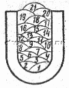
Fig. 7. The technique of surfacing of multilayer joints in arc welding of reinforcement with open arc bare wire of horizontal joints of rods (numbers indicate the order of surfacing of layers)
When welding horizontal bars of reinforcement, an alloying wire with a diameter of 2 mm is used. The sequence and pattern of movement of the wire when filling the groove is shown in Fig. 7.
In the process of fusion cutting, overheating of reinforcing bars is possible. To avoid this, it is recommended to conduct sequentially arc welding of the reinforcement of two to three joints. In this case, the cutting of the first joint is fused to 60–70% of its volume, after which they switch to the second joint, and then to the third. Having filled the third joint with weld metal 60–70% of the volume, they again go over to the first joint, fill its entire melting space with welded metal and weld the remaining joints in the same sequence. End the electric welding of the joint by surfacing two flank joints with a leg of 8-12 mm. The joints of the vertical bars of the reinforcement are welded in the same way as the horizontal ones. After fusion of the butt space, the flank seams are laid in the direction from top to bottom. The sequence of lining the welds is shown in Fig. 8.
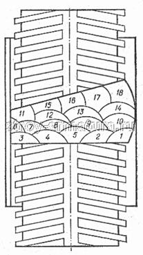
Fig. 8. The technique of surfacing of multilayer joints during welding of reinforcement with an open arc of bare wire of vertical joints of rods (numbers indicate the order of surfacing of layers)
With these methods of welding reinforcement with an open bare-arc (SODGP) for horizontal and vertical bars, the following classes of reinforcing steels are recommended (the diameter of the bars in mm is indicated in brackets): A-1 (20–40), A-2 (20–80), A-3 (20–40), At-3C (20–22), At-4C (20–28). The ratio of the diameters of the reinforcing bars (smaller to larger) should be in the range of 0.5–1.0. Steel of the class At-3C and At-4C should be welded on an overlay bracket extended to 4d.
Wire for mechanized arc welding of fittings
In mechanized submerged-arc welding, in shielding gases and without additional protection, with self-shielding wire and for welding with forced formation of a seam, electrode of continuous cross section and tubular (powder), which is a steel round cross-section, filled with powder, are used. The following grades of electrode wire are used for welding carbon and low alloy structural steels in shielding gases: Sv-08GS, Sv-12GS, Sv-08G2S, Sv-08GSMT. For welding with multilayer welds without additional protection for low-carbon, medium-carbon and low alloy steels, alloyed electrode wire of the Sv-15GSTYuTS and Sv-20GSTYuA grades is used.
Flux cored wire is used for both welding and surfacing. For the manufacture of cored wire, a strip of low-carbon steel of the 08KP grade cold rolled is used. Currently, the industry produces five types of cored wire (Fig. 9) with a diameter of 1.2–3.6 mm.
flux-cored wire of simple cross-section with one longitudinal slit flux-cored wire of simple cross-section with two longitudinal slots flux-cored wire of complex cross-section with one formed end of steel tape flux-cored wire of complex cross-section with two molded ends of steel tape flux-cored wire of tube section without longitudinal slotFigure 9. Cross section of cored wire of various types.
For arc welding of low-carbon, low alloy and medium alloy steels, depending on the welding method, various types and types of flux-cored wire are used: self-protective general-purpose wires of the grades PP-AN1, PP-AN7, PP-2DSK; general-purpose wires for welding in carbon dioxide of the grades PP-AN8, PP-AN21; self-protective wires for welding with forced formation of a seam, for example, grades PP-AN15, PP-AN19N, PP-2VDSK; wires for welding in carbon dioxide with forced formation of a seam of grades PP-AN5 and PP-ANZS.
Resistance spot welding
The main type of reinforcement of reinforced concrete structures are intersecting rods in the form of nets and flat frames. For welding of such reinforcing structures, as well as for lap welding of round reinforcing bars to elements of flat products (strip, angle and other steel), contact spot welding.
Resistance spot welding provides a number of advantages compared to other types of welding: the possibility of increasing labor productivity due to the lower complexity in the manufacture of reinforcing cages and meshes compared to electric arc welding; low energy consumption due to the use of hard welding modes using high current density for a very short period of time; the possibility of mechanization and automation of the process; lack of metal consumption (in electrodes).
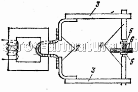
Figure 10. Contact spot welding of reinforcement
Scheme of current flow in contact spot welding: 1 - secondary turn of the transformer; 2 - copper tires; 3 - trunk; 4 - electrode holder; 5 - electrode; 6 - reinforcing bar
The essence of the process of contact spot welding of reinforcement is as follows. From the secondary turn of the welding transformer through copper bars, trunks, electrode holders and electrodes, the current is led to the intersection of the reinforcing bars sandwiched between the electrodes (Fig. 10). The electrodes are water cooled. The resistance at the point of contact of the reinforcing bars is many times higher than the resistance of the other sections of the chain, therefore it is at this point that heat is intensively released, which heats the metal of the reinforcing bars to a plastic state. Under the action of the compression force of the electrodes, they are welded.
To obtain welded joints of the required strength, it is necessary to perform welding in certain modes. The welding mode is selected depending on the diameter of the welded reinforcement and the grade of steel from which it is made. The correctness of the choice of welding mode is checked by a control test of the shear strength of welded samples of reinforcement.
If the strength of the welded joints of the reinforcement due to lack of penetration is less than required, then the current density or its flow time is increased. If the strength is insufficient due to burnout, these same indicators are accordingly reduced.
With insufficient current density, welding of the valves may not be possible even if the current flow time is very long; if the density is too high, the reinforcing bars may burn out.
The current density in resistance spot welding machines is controlled by switching the steps of the welding transformer, and the duration of the current flow is controlled by moving the pointer on the electronic time controllers.
For contact spot welding, special machines are used, which are divided into single-point, two-point and multi-point according to the number of simultaneously welded grid nodes and flat frames.
Machines for spot welding are stationary and suspended; with one-sided and two-sided current supply; with pneumatic and pneumohydraulic electrode compression mechanism. Control the duration of the current flow is carried out automatically.
In connection with the development of reinforced concrete construction in the direction of creating large reinforced concrete panels and other elements, the need arose for a large-scale assembly of reinforcing cages and meshes. For this purpose, mobile (hanging) welding machines have been created, since it is impossible to spot-weld such fittings on conventional welding machines due to its bulkiness and large mass.
Suspended welding machines are divided into two groups according to the design basis: with an integrated welding transformer and with an external one. All machines are made according to one scheme and consist of the following main units: a body with a handle, a welding transformer, a power pneumatic drive, an electrode part (pincers) and a suspension device that allows you to rotate the machine and pincers 360 ° around its axis.
Suspended machines with an external transformer, in addition, provide live cables.
Weldability
The weldability of carbon steel (GOST 380–71 *) is ensured by the manufacturing technology and compliance with all the chemical composition requirements for steel B and C. The supply of steel of group B with a guarantee of weldability is specified in the order and in the certificate. Steel containing more than 0.22% carbon in finished products is used for welded structures under conditions that ensure the reliability of the welded joint. Steel grades BCt1, BCt2, VStZ of all categories and all degrees of deoxidation, including those with a high content of manganese, and at the request of the customer, steel grades BSt1, BSt2, Bstz of the second category of all degrees of deoxidation, including with a high content of manganese, is supplied with a guarantee of weldability. The weldability of low-alloy reinforcing steel of all grades, except for 80C, is also provided by the chemical composition and manufacturing technology. Welding of thermally hardened reinforcing steel is not allowed due to its softening in the weld zone.
Reinforcing steel, thermally hardened, welded, has the index “C” in the designation of the brand. For example, the designation of welded reinforcing steel with a diameter of 14 mm of class At-4: 14At-4C GOST 10884 is 81, and welded steel with increased resistance to stress corrosion cracking is indicated by the index "SK", At-5SK. According to GOST 10922–75, the temporary resistance of welded joints of reinforcing steel of class At, made by contact-butt, contact-spot and seam-butt welding, should not be less than the minimum value of the rejection minimum,
Low-carbon steels (carbon content up to 0.22%) belong to the category of well welded by all types of welding in weak conditions without additional technological operations. Medium carbon steels (carbon content 0.23–0.45%) during the welding process require such additional operations. So, to increase the resistance of the weld metal to the formation of crystallization cracks, the amount of carbon in it is reduced by using welding electrodes with a low carbon content, as well as reducing the proportion of the base metal in the weld. Reducing the likelihood of the formation of quenching structures in the weld metal can be achieved by preliminary and accompanying heating of the products.
Table 4. Preheating of steels (before welding)
Table 5. Heat treatment of steels after welding
Low alloy steels containing less than 2.5% alloying components and up to 0.22% carbon, as a rule, have good weldability. The low-carbon steels of grades 18G2S, 25G2S, 25GS, 20HG2Ts used for the manufacture of reinforcement of reinforced concrete structures are classified as satisfactorily welded. These steels contain no more than 0.25% carbon. If the carbon content is greater than 0.25%, quenching structures and cracks may occur in the weld zone, as well as pore formation due to carbon burnout. In the table. 4 shows the recommended heating modes of heat-treated steels before, and in table. 5 after welding. It should be borne in mind that the recommended limit values \u200b\u200bof the weldability criteria of steels are unstable and may vary depending on the development of welding equipment and technology.
Resistance butt welding
Flash butt welding is an effective way to connect the rods, since it does not require melting electrodes for its implementation; provides high labor productivity, and also allows you to mechanize and automate the work process.
The disadvantage of flash butt welding is the possibility of its use only in stationary conditions due to the significant mass of welding equipment and the large consumption of electric energy.
The essence of the flash butt welding process is as follows. An electric current is connected to the welded rods and, bringing the latter into contact, form a closed electric circuit (Fig. 11).
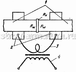
Figure 11. Electrical circuit in flash butt welding
1 - welded rods; 2 - clamping jaws; 3 - secondary turn of the welding transformer; 4 - primary winding of the welding transformer; Rm is the resistance of the welded rods; Rk - contact resistance
In this circuit, the junction of the rods has the greatest resistance to the flow of current, therefore, heat will be generated most intensively in this place, which will warm the ends of the rods to a plastic, and partially to a liquid state.
There are two methods of resistance welding:
flash contact flash welding
flash butt welding with intermittent fusion with preheating.
Contact butt welding of rods of hot-rolled steel reinforcing bars of classes A-2 ... A-4 (in any combination) should be carried out by intermittent reflow with heating. Steel class A-1 fittings must be welded by continuous melting; with insufficient machine power, they can also be welded by heating reflow.
To form the initial electric current at the ends of the reinforcement, it is necessary to remove paint or rust from them. If the reinforcing bars were cut off by a gas flame, then their ends are first cleaned of slag crust with a chisel or hammer. The quality of the welded butt joints is affected by the cleanliness of the contact surface of the rods with the clamping jaws of the machine.
The flash butt welding mode should provide equal strength welded rods with minimal energy and time consumption.
The main parameters of the welding mode are: current strength or density, duration of current flow, upsetting pressure, as well as the installation length, i.e. the sizes of the ends of the rods protruding from the electrodes.
Depending on the current density (current per mm2 of surface), two modes of butt contact welding are distinguished:
hard mode, characterized by a high current density for a small period of time (for rods of small diameters),
soft mode with low current density for a long period (for rods of large diameters).
The current density during continuous flash welding is –10 ... 50 A / mm2. The duration of the current flow varies from 1 to 20 s, depending on the diameters of the reinforcing bars; with increasing diameter, the duration of the current flow increases.
For the quality of the welded butt joint, the specific upsetting pressure on the end of the rod (kg / mm2) is also important; it is selected depending on the class of steel. Specific precipitation pressure for steel of class A-1 is 30 ... 50 MPa, classes A-2 and A-3 - 60 ... 80 MPa. The compression force of the reinforcing bars during heating should be 10 ... 12% of the draft pressure. The duration of arc closures and openings when preparing the rod for welding is selected within 0.3–0.8 s.
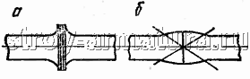
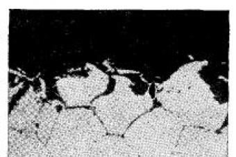
Figure 12. Appearance of butt joints of fittings made by contact electric welding with correct (a) and incorrect (b) welding conditions
The correct selection of the welding mode is approximately judged by the appearance of the welded joints (Fig. 12). With the correct mode of butt flash welding, the ends of the reinforcing bars warm up sufficiently and, with mutual compression, take the form shown in the figure. Confirmation of the correctness of the selected mode can be obtained only after laboratory tests of welded joints for strength.
In the process, the welder must monitor the condition of the contact jaws and periodically clean them from the appearance of soot. It is necessary to have a set of jaws of various shapes and sizes in order to avoid possible interruptions in operation when changing the diameters of the welded reinforcement.
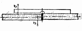
Figure 13. A template for checking the mixing of the axes of the rods in the joints made by resistance welding
Welded rods should be straight. The displacement of the axes of the rods in the joints allow no more than 0.1 of their diameter. The length of the rod is measured with an accuracy of 1 mm. The displacement of the axes at the junction is determined by a special template (Fig. 13). In addition to the external inspection, the joints of the fittings are tapped with a hammer weighing 1 kg; no rattling sound should occur.
Production of embedded parts
Embedded parts are made of reinforcing bars and rolled products (sheet and profile). Mild, well-welded steels are used, usually STZ Group B and C. One of the most common is a embedded part consisting of a steel plate and a reinforcing bar welded with a T-joint (Fig. 14).
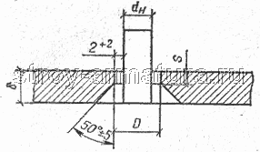
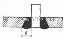
Fig. 14. T-joint of the anchor rod with the flat element of the embedded part with countersunk holes
The rod with the plate is welded using automatic welding machines such as ADF-2001UHL4. For T-bar connection of the rod with the plate, manual arc welding is used through a pre-countersink hole. After welding, the seam is flush with the plane of the plate. You can connect the plate to the rod in the horizontal plane (Fig. 15).
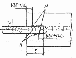
Fig. 15. Connections of rods with flat elements in the horizontal plane
H - the direction of welding; M - tack places
Often, the T-joint of the reinforcing bar with the steel plate is carried out by means of relief welding. In this case, contact relief welding can be performed at the end, i.e. the rod is welded perpendicular to the plane of the plate (Fig. 16) and lap. Reliefs on the plates are obtained using mechanical presses or press scissors. The reliefs are round or cylindrical in shape, and single or double in number. The welding mode is selected depending on the thickness of the connected elements of the embedded part and the number of welding points.
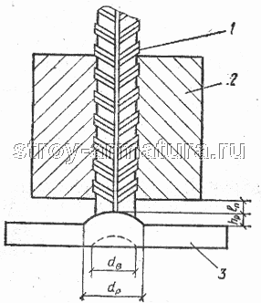
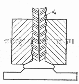
Fig. 16. T-joint by contact relief welding
1 - reinforcing bar; 2 - electrode; 3 - a flat element of the embedded parts; dв - diameter of the recess; dр - diameter of the base of the relief; dн is the diameter of the rod; hр - relief height; lp - rod stick out of the electrode
If it is not possible to use contact welding for lap joints, manual arc welding can be used. With the help of welding, the connection of embedded parts with elements of reinforcing structures is carried out. Depending on the class and grade of steel, the position of the axes of the connected elements and the type of weld (horizontal, vertical, lower), the welding method is selected: contact (spot, embossed), bath, arc (multi-electrode, multi-layer, spot, suture submerged).
Developed new design and technological solutions related to the manufacture of embedded parts. Stamped and stamped-welded embedded parts appeared, which made it possible to reduce steel consumption by 1.5–2 times and increase labor productivity by several times. A stamped embedded part is a product in which the plate (table) and the anchor (rod) are integral. They are cut out from the same strip with a special stamp. Bending of stamped strips (anchors) and plates is carried out using bending dies. Production of stamped embedded parts. can be fully automated. The technological process for the production of stamped parts provides for: cutting down; punching holes; relief planting (puklevka); incision of anchors; bending; metallization. Some operations can be combined, such as punching, punching, and planting relief. A great effect is also given by the combination of stamping and welding of embedded parts. In this case, the anchor is connected by welding with a specially prepared stamping relief plate.
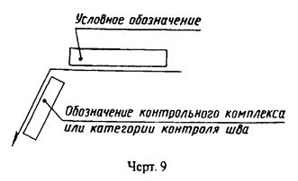
5. Conventional images and designations of weld joints in the design documentation
invisible - by a dashed line ( heck. 1g).
The visible single welded point, regardless of the welding method, is conventionally depicted by the “+” sign ( heck. 1b), which is performed by solid lines ( heck. 2).
Invisible single dots do not represent.
From the image of a seam or a single point, a leader line is drawn, ending with a one-way arrow (see heck. 1) The leader line is preferably drawn from the image of the visible seam.
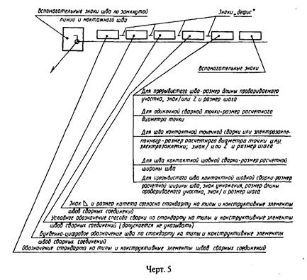
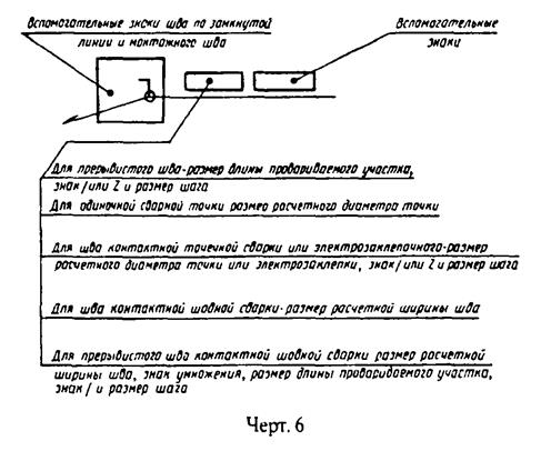
Symbols for welds
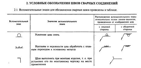
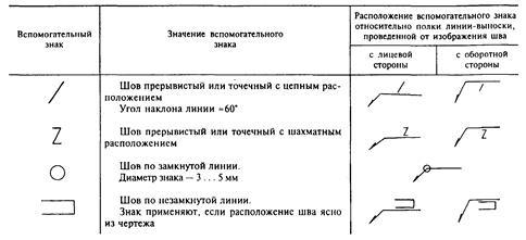
Auxiliary signs for welds
Notes:
1. For the front side of the unilateral seam of the welded joint, take the side from which welding is performed.
2. For the front side of the bilateral seam of the welded joint with asymmetrically prepared edges, take the side from which the main seam is welded.
3. For the front side of the bilateral seam of a welded joint with symmetrically prepared edges, either side can be taken.
In the joint designation, auxiliary signs are made in solid thin lines.
Auxiliary signs must be the same height as the numbers included in the seam designation.
The sign | _ \\ is performed by solid thin lines. The height of the sign must be the same as the height of the numbers included in the seam designation.
In the technical requirements of the drawing or table of seams indicate the method of welding, which should be performed non-standard seam.
Note. The contents and dimensions of the seam table columns are not regulated by this standard.
The technical requirements or the table of seams in the drawing provide a link to the relevant regulatory and technical document.
It is allowed not to specify welding consumables.
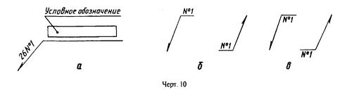
The number of identical seams can be indicated on a leader line with a shelf with a designation (see heck. 10 a).
Note. Seams are considered equal if:
their types and sizes of structural elements in cross section are the same;
they have the same technical requirements.
List of references
1. Manual arc welding, the book was written by a team of authors: chapter 25 I.G. Getia, the remaining chapters - V. And., Miller with the participation of B.D. Malysheva
2. Alekseev E.K., Melnik V.I. Welding in industrial construction - M Stroyizdat, 1977 –377 s
3.Aleshin N.P. Shcherbinsky V.G. Quality control of welding works - M Higher School, 1986 - 167 s
4.http: //www.stroy-armatura.ru
5. Interstate standard GOST 2.312–72 * “Unified system for design documentation. Conventional images and designations of welded joints ”(approved by the resolution of the State Committee of Standards of the Council of Ministers of the USSR dated May 10, 1972 No. 935)
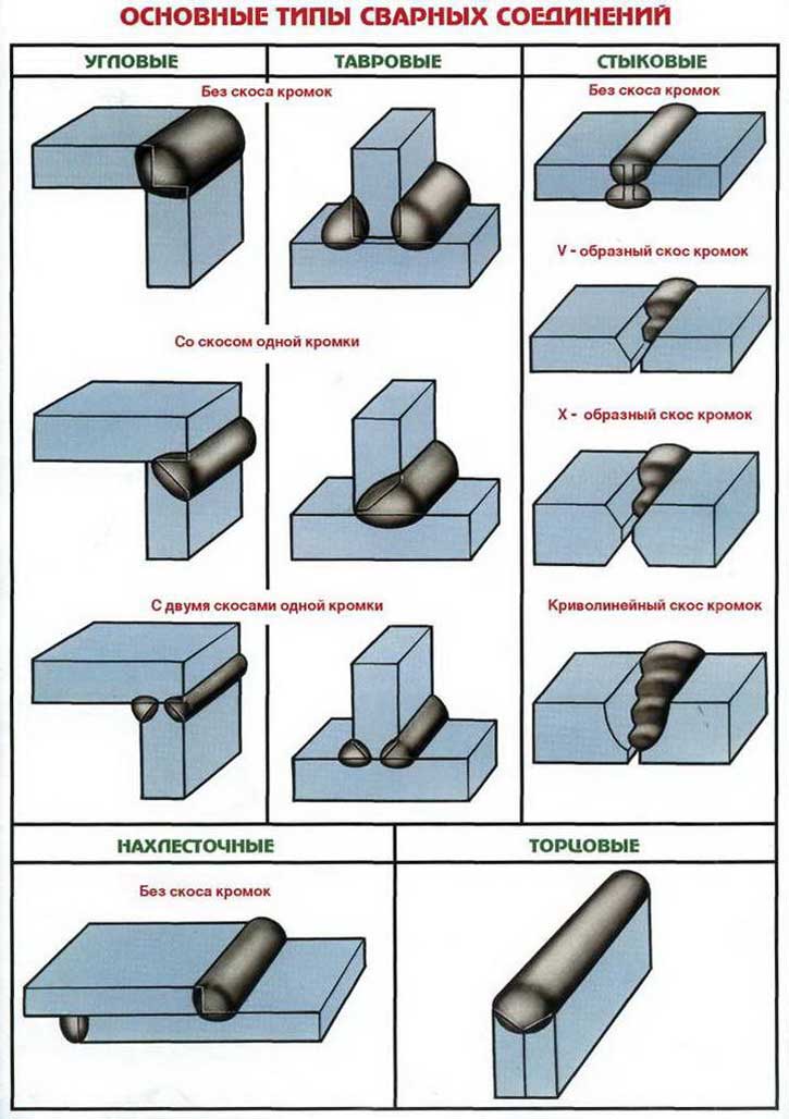
There are the following main types of welded joints: butt, lap, tee, corner, slotted, butt, with overlays, electro rivets.
Butt joints (Fig. 10) are the most common for almost all welding methods, since they give the lowest intrinsic stresses and strains during welding (for details on welding strains and stresses, see chapter VIII).
Butt joints are mainly used for sheet metal structures. They require the least consumption of the base and deposited metal and welding time; they can be made equal to the base metal. However, when making butt joints, careful and sufficiently accurate preparation of the sheets for welding and fitting them to each other is necessary.
With manual arc welding of steel sheets with a thickness of 4-8 mm, the edges can be cut at right angles to the surface. In this case, the sheets are placed with a gap of 1-2 mm.
Without beveling, the edges can be “butt welded” up to 3 mm for single-sided and up to 8 mm for double-sided welding.
Sheets from 4 to 26 mm thick with manual arc welding are joined in joint with a one-sided bevel of edges. This type of edge preparation is called V-shaped. Sheets with a thickness of 12-40 mm and more are connected with a two-sided bevel of the edges, called the X-shaped.
The blunting of the edges is done in order to prevent the flow of metal during welding (burn-through). The gap between the welded edges is left to facilitate the penetration of the root of the seam (lower parts of the edges). Of great importance for the quality of welding is maintaining a uniform gap width along the entire length of the seam, that is, observing the parallelism of the edges.
Two-sided beveling of edges (X-shaped) has advantages over one-sided (V-shaped), since with the same thickness of the sheets to be welded, the volume of deposited metal will be almost
half as much as with a one-sided bevel. Accordingly, the consumption of electrodes and electricity during welding will decrease. In addition, two-sided beveling of the edges gives less warping and residual stresses during welding than one-sided
With manual arc welding of steel with a thickness of more than 20 mm, the bevel angle between the edges can be reduced from 60 to 45 °. The gap between the blunt edges should be equal to 4 mm, which facilitates proper penetration of them. A decrease in the bevel angle of the edges leads to a reduction in the volume of the deposited metal, and therefore to an increase in welding productivity and saving of electrodes.
The edges of sheets of unequal thickness, joined in a joint, are chamfered as shown in Fig. 10b, moreover, the thicker sheet is beveled to a greater extent.
When connecting steels of large thicknesses, in order to reduce the amount of deposited metal, in a number of cases they resort to a bowl-shaped form of edge preparation: for thicknesses from 20 to 50 mm, one-sided and more than two-sided (Fig. 10, c).
Lap joints (Fig. 11, a) are primarily used in the arc welding of steel structures with a thickness of not more than 10-12 hp. They do not require special edge processing, except for trimming them. With this connection, it is recommended that the sheets be welded on both sides, since with one-sided moisture can enter the gap between the sheets and subsequent rusting of the metal in this place.
Assembly of the product and preparation of sheets during lap welding are simplified, however, the consumption of the base and deposited metal is greater than when welding in butt. In case of roller and spot contact welding, only lap joints are used.
T-joints (Fig. 11, b) are widely used in arc welding; are performed without bevelled edges and with beveled edges on one side or on both sides. The vertical sheet should have a fairly equally trimmed edge. With a one-sided and two-sided bevel, the edges of the vertical sheet between the vertical and horizontal sheets leave a gap of 2-
3 mm for better penetration of the vertical sheet over the entire thickness. One-sided beveling is used if the product design does not allow welding of the T-joints on both sides.
Corner joints are used for welding various pre-processed sheet edges and are shown in Fig. 11, c. The parts to be welded are located at a right or other angle and are welded along the edges. Such joints are mainly used in welding tanks operating under low internal gas or liquid pressure. Sometimes angular joints are also boiled from the inside, as shown by the dotted line in Fig. 11, in (left).
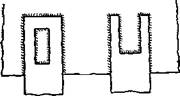
Slotted joints (Fig. 11, d) are used when the length of a normal lap seam does not provide
|
|
|
|
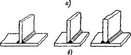
Fig. 12 Welded joints: a - butt, or side, b-with overlays, c - electro-rivets //
exact strength. Slotted joints are closed or open type. The slot is usually performed by oxygen cutting.
End, or side, connections are shown in Fig. 12 a. Sheets are joined by their surfaces and welded at adjacent ends.
Connections with pads are shown in fig. 12,
b. The overlay 2, overlapping the joint of sheets 1 and 3, is welded along the lateral edges to the surface of the sheets. These compounds require additional metal consumption for the pads and therefore are used only in those cases when for some reason they cannot be replaced by butt or lap joints.
The electro-rivet connection is shown in fig. 12, e. With the help of electric rivets, durable but not tight joints are obtained. The top sheet is drilled and the hole is welded so that the bottom sheet is captured. During automatic submerged arc welding, the top sheet, if its thickness is small, is not pre-drilled and it is fused with a welding arc.
The described joints are typical for manual arc welding of steel. In gas welding, submerged arc welding, welding of low-melting non-ferrous metals and in other cases, the shape of the edges may be different. The corresponding information about them will be given in subsequent chapters when describing these welding methods.
Welds are divided into the following groups:
1. By position in space - lower, horizontal, vertical and ceiling (Fig. 33, c). The simplest to perform is the bottom seam, and the most difficult is the ceiling. Ceiling welds can be performed by welders who have specially mastered this type of welding. Perform ceiling seams arc welding is harder than gas. Welding horizontal and vertical seams on a vertical surface is somewhat more difficult than welding the bottom seams.
2. In relation to the current efforts - flank, frontal, or frontal, combined n oblique (Fig. 13, b).
3. In extent - continuous, or continuous, and intermittent (Fig. 13, c). Intermittent seams are used in cases where the joint should not be tight, and, based on the strength, a continuous seam is not required.
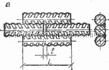
For an intermittent seam, the length of its individual sections (/) is from 50 to 150 mm; the distance between the sections of the seam is usually 1.5-2.5 times the length of the section; the value of t is called the seam. Intermittent welds are used quite widely, as they save deposited metal, cost and welding time.
4. According to the degree of convexity, they are normal, convex and concave (Fig. 13, d). The bulge of the seam a "depends on the type
|
|
a- according to the position in space, b- relative to the acting force, c along the length of the stn, d- according to the degree of convexity of the surface of the seam
applied electrodes: thinly coated electrodes give a seam with a large bulge; with thick-coated electrodes, due to the greater fluidity of the molten metal, normal welds are usually obtained.
|
|
Studies have shown that welds with a large bulge do not increase the strength of the weld, especially if the weld is subjected to varying loads and vibrations. This is due to the fact that with welds with a large bulge it is impossible to obtain a smooth transition from the weld bead to the base metal and at this point something like a “cut” of the weld edge is formed, where a significant concentration of stresses occurs.
Therefore, under the action of variable, shock or vibration loads, the destruction of the welded joint can begin from this place. Seams with a large bulge are uneconomical, since more electrodes, time and electricity are spent on their implementation.
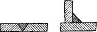
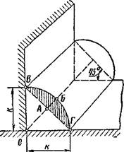
5. According to the type of connection - butt and corner (shaft
Fig. 14, Corner (roll) seam). Corner seams apply - "
with joints in overlap, end-to-end, corner joints and joints with overlays. The side to the fillet weld (Fig. 14) is a leg. The hatched area AVBG characterizes the degree of convexity of the seam compared to normal and is not taken into account when determining the strength of the welded joint. The fillet welds are made so that their legs are equal, that is, OG - OG \u003d k. The angle between the sides of the OG and the OG is 45 °.