Methods for determining quality welds conducted in accordance with construction standards and specifications. Current weld testing methods provide the ability to detect almost any flaws that occur during welding.
The following standards for welds determine the conditions for assessing the quality of welds, which are made using arc, argon, electroslag and gas welding.
Standards for determining quality are adopted according to the checks below.
Visual and measuring control.
For visual and measuring inspection of welds, the following are not permissible:
1. Cracks of any types and directions.
2. Lack of penetration between the supporting metal and the seam, as well as between the seam rollers.
3. Lack of penetration at the root of the seam.
4. Sag and smudges, splashes of metal.
5. Unfilled craters.
7. Burns.
8. Clusters.
9. Undercuts.
10. Deviations in weld dimensions are higher than accepted standards.
Norms of permissible flaws detected during visual and measuring inspection.
Capillary control.
When checking the weld for indicator prints, elongated and not single indicator prints are not allowed. The total number of single rounded indicator prints should not exceed the norm for welds for single inclusions, and the limit size of each indicator print should not be more than three times the value of these standards. Defects noticed during the inspection are allowed to be assessed by their actual result after washing off the reagents. In this case, you must adhere to the requirements of visual and measuring inspection of welds.
Magnetic particle control.
Quality assessment standards during magnetic particle testing should be consistent with visual inspection standards. Defects noticed during the verification process are allowed to be evaluated according to their actual sizes after washing off the emulsion or powder.
Radiographic control.
The quality of the welds is acceptable if various imperfections, cracks, burns, fistulas, impermissible convexity and concavity of the root of the seam are not detected on the radiographic image, and the size, number and total area of \u200b\u200bsingle inclusions and clusters will not exceed the standards shown in the table below.
Ultrasonic inspection.
The quality of the welds is acceptable when the following conditions are met:
1. Noticed discontinuities are not elongated.
2. The gap along the scanning plane between two adjacent discontinuities should be no less than the conditional length of discontinuities with a large value of this indicator.
3. The equivalent area and the number of single discontinuities should not exceed the standards indicated in the normative document.
Mechanical tests.
The quality of the welds according to the results of a mechanical check is acceptable when the following conditions are met:
1. The temporary resistance should have indicators not lower than the minimum indicators for this metal product. And when checking welds with different values \u200b\u200bof temporary resistance, this indicator should be no less than the minimum allowable for a less durable metal.
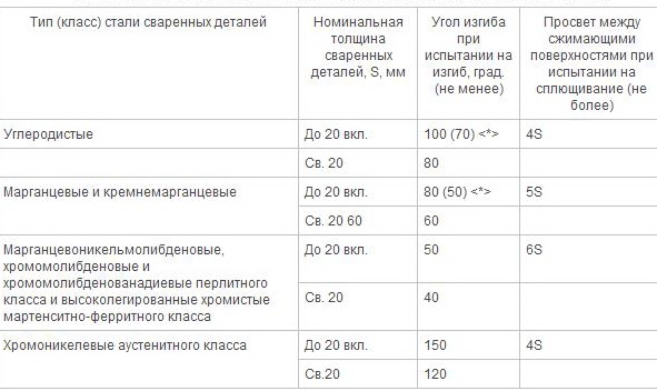
2. The bending angle during the test for static bending and clearance between the compressing planes, when checking for flattening of the welding joints of pipes with an external diameter of less than 108 mm with a wall thickness of less than 12 mm, must be in accordance with the standards.
3. Impact strength during the test for impact bending of specimens of type VI according to GOST 6996-66 with a notch along the seam should be not less than:
a) 49 J / cm 2 (5 kgf-m / \u200b\u200bcm 2) for steels of high alloy martensitic-ferritic, as well as pearlite classes.
b) 69 J / cm 2 (7 kgf-m / \u200b\u200bcm 2) for austenitic chromium-nickel steels.
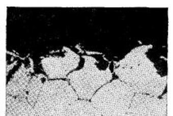
Metallographic studies.
The standards for assessing the quality of welds based on the results of metallographic inspection should be in accordance with the conditions of ND. Along with this, impermissible flaws are defects indicated in the second figure.
Today, welding is a very popular type of joint. It is applicable for small parts, and for large products, and for mass construction, and with varying degrees of complexity. The technology of welding metal structures allows you to use absolutely any type of joints: angular, tee, lap or butt. And this is not all, because technologies do not stand still, they are developing, which means that welding itself is becoming more advanced.
Requirements for welding metal structures
Today, welding works have their own nuances. It is one thing when an amateur at home is engaged in welding, and quite another when professional metal production is in progress. In the second case, the quality of work will depend on many factors.
There are certain sections that govern the entire technology:
- SNIP ІІ 23-81 and GOST 27772-88. This section focuses on the details. Here, the possibility of using certain metals for structures, geometric shapes, strength categories, and also the weldability of each metal are described in detail.
- There is a section on circuits. Here you can get acquainted with how to properly create seams, because the strength of the entire structure depends on their quality. Depending on the number of parts to be welded, the complexity of the work itself will depend.
- Welding qualification. There are levels of work that even a novice can do, but there are categories that only a professional welder can handle. A more detailed list can be found in document RD 15.132-96 of the Ministry of Fuel and Energy of the Russian Federation.
- Welding control. This parameter qualifies the section of any GOST for welding metal structures.
Of course, these standard requirements are more related to the professional level of welding, but if there is a desire to develop in this area, then it will not be superfluous to get acquainted with this for a simple beginner. In addition, these documents will help to correctly determine the material for the structure, the type of connection, people who can perform certain types of welding, determine the very control of welding.
If a beginner or just an amateur takes this question, then you can use the help of a designer.
Classical technology for welding metal structures
If we act in the old manner, then in such technology only two sources of energy will be used: an electric arc and a gas flame.
Both arc and gas welding make a seam in three ways:
- do it yourself;
- automatically;
- semi-automatically.

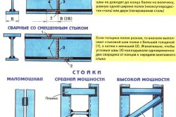
Welding schemes: a - back in a stepped way; b-way "double layer"; in - a hill; g - cascade.
Regarding the first mode, several points should be noted. In this version, all work is performed manually. That is, it is independently formed weld, the welding process and electrode feeding are controlled. This method uses the technology of simple electric arc welding, submerged arc welding, soldering using a gas welding apparatus. But there is immediately a nuance that manual welding is acceptable only in household use.
Automatic welding is so named because the entire process of welding seams is carried out without human intervention. The apparatus used itself has a special mechanism, which is each time adjusted depending on the type of operation required. Each model of such automation has its own limitations, which are mainly indicated in the instructions for the technique. Most of all, automatic welding is used in mass production, since, thanks to it, the cost of such work with metal becomes quite low.
Such a device allows you to work with, apply electroslag welding, all possible options are manual type. Regarding the latter option, it is immediately worth noting that the operator is replaced by a robot.
Semi-automatic version has its own peculiarity. In this case, the seam is applied manually, but the wire or electrodes are automatically fed. This technology allows you to increase the level of performance several times. And the most convenient thing in such devices is that they combine all the methods of automation and manual technologies. That is why such a regime is popular among both "home" craftsmen and professionals.
Innovations in welding technology
Today the world does not stand still and is constantly evolving in all directions. The same applies to welding processes. This includes the use of a laser, and the thermal effect of friction, and the strength of the electron beam, and ultrasound.
Each of the new products helps operators to work faster and easier with metal structures. The following technologies are especially popular:
- termite;
- plasma
- electron beam.
Each technology has its own characteristics, so it is used in production.
The first type is applicable for welding and installation of metal structures, when the contours of the seams of the parts are treated with a special mixture, which is introduced to the joints at the time of combustion. The convenience of this technology lies in the fact that it even allows you to work with cracks in structures. To do this, use the method of "influx" of metal.
Plasma technology is used only with the use of ionized gas, which is passed between two electrodes. The gas itself acts as an electric arc, but the effect itself is much stronger. With the help of superheated gas, metal of absolutely any thickness is melted, while there is the possibility, if necessary, to cut it. Thus, a multifunctional, automatic welding system is created around the plasma generator.
The latest technology allows you to work with deep seams, up to 20 cm. But in this case, the following ratio of the depth of immersion of the beam and the width of the seam should be present - 20: 1. But vacuum is important for electron beam technology. Accordingly, it is very difficult to use such a generator in household use. Therefore, they are used only in highly specialized fields.
As is clear from the foregoing, each type of welding is applicable in a particular field of work. For example, for "home" welding it is not rational to use automatic technology. It is quite expensive, which means it will pay off too long. But for the same farm work, for example, the construction of a hangar or other similar construction, a semiautomatic device or automation is just a viable option.
Welding structures: features
Welding technology is applicable not only to metal, with it you can also work with plastic and other polymers. Welding itself implies such a process during which the melting and deformation of individual working parts takes place, after which they are combined into a single whole.
Welding works have two main stages: assembly and connection.
The first stage is quite complicated and at the same time laborious. For the final design to be truly reliable, it is essential that all requirements are met in the proper order. If objectively assessed, it is precisely the assembly of the structure that accounts for more than half of the total time spent.
But to speed up the whole process, you only need to use a number of recommendations.
How to ensure the correct assembly of the structure?
Observing certain requirements put forward for the assembly of structures, high-quality performance of all further work is ensured:
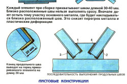
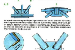
- When choosing parts, you should adhere to all sizes that were originally laid down in the project. Otherwise, the design will at least have an inappropriate appearance, and at most not fulfill its direct functional purpose.
- Focusing on the initial design, all elements should be in place.
- The size of the gaps also plays a very important role. If there are more of them, then this will significantly affect the strength of the product, and if less, this can lead to malfunctions of movable parts.
- Since there are always angles in the structure, they should be controlled using special tools. It is very important that during the assembly process all angles between the planes are straight, where it is so necessary. In the opposite case, this threatens an imbalance of the whole structure, and even such a product at a fine moment can develop like a house of cards.
- It is very important to ensure butt joints space for permissible displacement of elements.
All these points are very important to consider and control throughout the assembly, especially if welding will be carried out in automatic mode. Indeed, welding in the process of performing work can be corrected, which is very difficult to do with automation. Although automatic welding is convenient in that it eliminates the influence of the human factor, it means that there will be much less errors in the finished design.
Positive aspects of welding
In addition to the fact that welding saves time significantly, and the seam itself is much better, it also has other positive characteristics:
- Since in this process only two working elements are involved, without any additions, the mass of the finished solder remains the same as it was originally. It also saves on working material.
- Welding has no restrictions on the thickness of the material. It all depends on the use of this or that equipment.
- The variety of modern welding machines allows you to work with completely different materials, while they provide high quality weld, even if the work was carried out with such complex metal as aluminum.
- During welding, it is very easy to control, and if necessary, adjust the shapes of finished structures.
- A very important advantage is the saving of financial resources and time spent on the work.
- The more complex the type of welding, the more difficult it is to complete the type of structure. At the same time, it is possible to use cast or stamped parts, and the type of metal does not make much difference, whether it is aluminum or steel.
- The welding equipment itself is quite affordable today both in terms of price and in terms of the possibility of purchasing it. At the same time, when choosing the right technology, you can have a high rate of performance.
- If desired, there is always the opportunity to create a production line type.
- If there is a desire and opportunity, you can create a design using non-standard materials: ultra-pure metals, aluminum or steel alloys, etc.
- If it becomes necessary to work with small parts, welding will not interfere with this. It is applicable to them.
- Welding is also used for repair purposes. This allows you to quickly return the mechanisms and equipment to "life".
- If, then you can be sure that all joints will have high tightness. Of all the methods of connecting the elements, only welding has the highest rate for this characteristic.
Additional points
But for all the work to be carried out efficiently and at the proper level, it is important to comply with all the requirements for the technology of production of metal structures.
Properly selected equipment and its components will ensure high quality seams. Otherwise, not only the joints, but the entire finished structure may have an unpresentable appearance.
The main thing is that wrong seams threaten the occurrence of unpleasant situations: they can break up, burst, crack. And this in turn will lead to additional repair work. And it’s good if nobody suffers from such a “defect,” but it can happen and vice versa.
That is why, before undertaking independent welding, it is better to consult with relevant specialists on this issue.
Ministry of Fuel and Energy of the Russian Federation
(Ministry of Fuel and Energy of Russia)
State Committee of the Russian Federation for Housing and Construction Policy (Gosstroy of Russia)
Approved by
Ministry of Fuel and Energy of Russia
March 14, 1996 Approved
Ministry of Construction of Russia
May 20, 1996
Guidance document
RD 34 15.132-96
Welding and quality control welded joints metalwork
buildings during the construction of industrial facilities
BBK 38.634
C24
UDC 69.057.4: 621.791.052: 658.562
Developer OJSC "Orgenergostroy"
Compiled by: S.S. Jacobson, Cand. tech. sciences; N.D. Kurnosova, Cand. technical sciences; G.S. Zislin, Cand. technical sciences; M.L. Elyash, Ph.D. tech. of sciences
Approved by Deputy Minister of Fuel and Energy of the Russian Federation Yu.N. Korsun 03/14/96 and Deputy Minister of Construction of the Russian Federation S.I. Poltavtsev 05/20/96
The guidance document (RD) defines the organization and technology of welding work during the construction of metal structures of industrial buildings, as well as the volume, control procedure and standards for assessing the quality of welded joints.
RD 34 15.132-96 covers the following types of welding: manual arc with piece electrodes, mechanized (semi-automatic) welding with self-shielding flux-cored wire and in carbon dioxide, automatic and mechanized submerged arc welding.
RD 34 15.132-96 is designed for workers involved in welding and assembly of large construction projects
1. GENERAL
1.1. Purpose and scope
1.1.1. This guidance document (RD) is intended for personnel engaged in the assembly and welding operations during the enlargement and installation of metal structures of industrial buildings.
Fulfillment of the requirements of this RD for the organization and technology of assembly and welding of metal structures ensures the production of welded joints that meet the quality indicators established by the standards, with minimal labor costs. RD is the guiding document in the development of work projects and other technological documentation.
1.1.2. RD applies to manual arc welding with piece electrodes, mechanized (semi-automatic) welding with self-shielded flux-cored wire and in carbon dioxide, automatic and mechanized submerged arc welding in a construction site.
1.1.3. This RD defines the technology of assembly and welding works during enlargement and installation of metal structures made of carbon and low alloy steels according to GOST 27772:
shaped hire (corners, I-beams, channels) - from steel С235, С245, С255, С275, С285, С345, С345К, С375;
sheet, universal rolled products and bent profiles - from steel С235, С245, С255, С275, С285, С345, С345К, С375, С390, С390К, С440.
Designation of steels according to GOST 27772 (yield strength) and the corresponding steel grades according to other applicable standards are given in Appendix 1.
RD acts in conjunction with the following regulatory and technical documents (NTD):
SNiP 3.03.01-87. Bearing and enclosing structures;
SNiP II-23-81 *. Design Standards. Steel structures. M., 1991.
1.1.4. The guidance document contains the main provisions for the organization of welding at construction sites, guidance on the selection of welding materials and equipment;
requirements for assembly and welding of structural elements, welding modes, control procedure and standards for assessing the quality of welded joints.
In addition, this RD provides recommendations on the welding technology of individual standard, most commonly encountered steel structures.
1.2. Qualification requirements for welders, supervisors and engineers
1.2.1. Welding of metal structures of buildings of industrial facilities should be carried out by welders who have certificates for the right to carry out the corresponding welding work, issued to them in accordance with the requirements of the "Rules for the certification of welders", approved by the State Technical Supervision of Russia.
Welders with a tensile strength of 390 MPa (40 kgf / mm2) and more are allowed to weld structures with steels with a certificate of the right to work on welding these steels.
Mechanized welding methods are allowed for welders-operators who have passed a special course of theoretical and practical training and have passed tests for the right to carry out these works.
Welders of all specialties and qualifications must pass the tests for the 2nd qualification group for electrical safety. In addition, all welders must pass fire and safety tests.
1.2.2. A welder who first starts welding in this organization must, before being admitted to work, regardless of whether he has a certificate for the right to carry out the relevant work, weld test (permissible) samples. Welding of test samples should be carried out under conditions identical to those in which welding of structures will be performed.
The design and number of test samples are set by the welding manager depending on the types of production joints and the qualifications of the welder. The quality of test welded joints is determined by visual inspection to determine the continuity and formation of the seam, and if necessary (at the discretion of the head of welding), using non-destructive physical control methods.
The quality of test welded joints must be evaluated according to the standards provided for the same production joints. Test joints must be identical or of the same type with respect to those production joints that the welder under test will weld. Characteristics of welded joints of the same type are given in the "Welder Certification Rules".
1.2.3. Welders are allowed to those types of work that are indicated in the certificate. The certificate must list the steel grades or groups of steel grades in accordance with the "Rules for the certification of welders", the welding of which is allowed by the welder.
1.2.4. For welding at temperatures below minus 30 ° C, the welder must first weld test butt samples at a temperature not higher than that specified. With satisfactory results of mechanical testing of test samples, the welder can be allowed to weld at a temperature of 10 ° C below the temperature of welding of test samples.
1.2.5. Welding should be supervised by a person who has a document on special education or training in the field of welding.
Engineering management, having studied this RD, the relevant Construction Norms and Regulations, working drawings of products, production and technological documentation (PTD) for welding and methodological control are allowed to supervise welding, control of welded joints and operational control. Engineering knowledge and their professional training in welding production should be checked by a commission appointed by order of the head of the enterprise. Engineering knowledge is checked at least once every three years.
1.2.6. The quality control of welded joints is allowed to be carried out by inspectors who have passed a special program of theoretical and practical training and received a certificate for the right to perform work on defectoscopy of welded joints with the appropriate type (method) of control. Controllers for physical control methods must be certified in accordance with the "Rules for the Certification of Non-Destructive Testing Specialists" approved by the State Technical Supervision Service of Russia on 08/18/92.
1.2.7. The training of supervisors should be carried out by special educational institutions or units of professional training (educational combines, centers, courses, etc.) of enterprises that perform welding quality control work and are licensed to carry out such work.
The training of controllers should be specialized in control methods (ultrasonic diffectoscopy, radiography, etc.), and, if necessary, in types of welded joints, which should be indicated in their certificates. Each controller can be allowed only to those control methods that are indicated in his certificate. The inspector who has had a break in work (for this type of control) for more than 6 months must again pass the exams in full.
1.3. The main provisions of the organization of welding
1.3.1. When developing a project for the production of works (PPR) for the installation of metal structures of buildings, the conditions for assembling structures for welding, welding and control of welded joints should be taken into account and reflected.
The most progressive technology of assembly and welding operations with the optimal level of mechanization should be incorporated into PPR.
1.3.2. When organizing and performing assembly, welding and quality control of welded joints, all conditions must be created to comply with safety and fire safety rules in accordance with the requirements of the following regulatory documents:
SNiP III-4-80. Safety measures in construction;
GOST 12.3.003. Occupational safety standards system. Electric welding works. Safety requirements;
"Rules for the installation of electrical installations";
"Rules for the technical operation of electrical installations of consumers";
"Safety regulations for the operation of electrical installations of consumers";
"Sanitary rules for X-ray inspection", No. 2191-80;
"Sanitary rules for radioisotope flaw detection", No. 1171-74;
"Sanitary rules for welding, surfacing and cutting of metals", No. 1009-73;
"Fire safety rules during welding and other fire works at the facilities of the national economy";
"Fire safety rules during construction and installation works. PPB 05-86."
1.3.3. The organization performing assembly and welding operations must ensure the proper quality of welded joints due to:
use of serviceable equipment;
the use of welding materials of appropriate quality that have passed the appropriate control;
fulfillment of technological requirements for assembly and welding of products regulated by the PDD;
performing operational control of assembly and welding processes;
timely quality control of finished welded joints.
1.3.4. The use of basic materials (sheets, profiled steel) and welding materials (electrodes, welding wire and fluxes) that differ from those specified in the production and technological documentation (PDD) can be allowed by a joint technical decision of the PDD developer organization, an industry specialized organization and organization - the manufacturer of the work.
1.3.5. The assembly procedure and enlargement of the mounting blocks and the sequence of work should ensure the possibility of applying the most advanced welding methods. To ensure the proper quality of welded joints and to increase labor productivity during assembly, welding and quality control of welded joints, one should be guided by the provisions set forth in this section.
1.3.6. The method of welding metal structures at different stages of their enlargement and installation should be determined by the project of works (PPR).
When choosing a welding method, keep in mind:
the advisability of using mechanized welding methods should be confirmed by a feasibility study;
automatic submerged arc welding should be used for large-scale assembly of structures for joints of considerable length;
mechanized (semi-automatic) welding with self-shielded flux-cored wire can be used in the enlargement and installation of metal structures for welding seams in the lower, inclined and vertical positions;
mechanized (semi-automatic) welding in carbon dioxide (solid wire) should be used for enlarging and assembly welding of metal structures in any position of the weld, provided that the welding site is protected from wind.
In cases where automatic and mechanized welding cannot be used, manual arc welding should be used.
1.3.7. The number of welding engineers and technicians for mechanized welding equipment at a construction site depends on the volume of welding work and the number of welders working. It is installed in accordance with the regulations on the welding service of the construction and installation organization.
1.3.8. Power supply of the enlargement site and the territory of the building to be reconstructed or reconstructed for welding purposes should be carried out using electric current distributions to all sections of the enlargement site and the building to be installed.
1.3.9. The wire section for connecting the power source for welding to the network should be selected according to the table. 1.1. In manual arc welding, the electrode holder is connected to the welding circuit with a flexible copper wire with rubber insulation of the PRD, PRI, KOG 1, KOG 2 brands, the cross section of which must be selected depending on the welding current: at a current of up to 100A - at least 16 mm2, at 250A - 25 mm2, at 300A - 50 mm2. The length of the flexible wire should be at least 5m.
Table 1.1
Wire cross section for connecting welding current sources to the network
Maximum welding current Cross section of copper * wire, mm2, at mains voltage V
power source, A 220 380
300 16 10
500 35 16
1000 70 50
2000 - 120
4000 - 240
__
* The cross section of the aluminum wire should be 1.5 times larger
1.3.10. With a large amount of assembly and welding operations, the supply of the assembly sites and the building under construction with oxygen and combustible gas for cutting should be carried out centrally using wiring from the power center to the cutting stations. Expediency of application centralized system power should be confirmed by calculation.
The distribution of oxygen and combustible gas over the building of a large industrial facility should be provided for in the project as a permanent gas supply system remaining after construction to complete repair work during the operation of the facility.
Centralized gas distribution at the construction site is carried out as a temporary gas supply in accordance with the PPR.
1.3.11. Depending on local conditions, acetylene, propane-butane or natural combustible gas are used as cutting gas for cutting. Acetylene for cutting is used only at a considerable distance from the construction of refineries and natural gas pipelines, when it is technically impossible or economically impractical to use propane-butane or natural gas.
1.3.12. The construction sites are supplied with oxygen from their own stationary oxygen plants (such as KGN-30, 2KG-30, etc.), or from a gasification station, where liquid oxygen delivered to an object in railway or automobile tanks is gasified and routed through a gas pipeline to workplaces or in an oxygen train. The method of supplying oxygen depends on local conditions and must be confirmed by calculation.
1.3.13. The supply of liquefied propane-butane should be carried out using special automobile tanks of the supplier plant. Underground tanks are being built at construction sites where propane-butane is stored; gasified propane-butane is fed from reservoirs to places of consumption.
1.3.14. Design, construction, testing and operation of oxygen and combustible gas pipelines should be carried out in accordance with the “Safety Rules in the Gas Industry” (Gosgortekhnadzor, 1992).
1.3.15. The welded surfaces of the structure and the welder's workplace must be protected from rain, snow, wind and drafts.
At an ambient temperature below minus 10 ° C, it is necessary to have an inventory room for heating near the welder's workplace, and at a temperature below minus 40 ° C, welding should be done in a heated teapot, where the temperature should be above 0 ° C.
1.3.16. At each construction site, a warehouse should be equipped in a warm, heated room for storing welding material (electrodes, wire and flux). In the warehouse, the temperature must be maintained at least 15 ° C, while the relative humidity should not be more than 50%.
Welding materials should be stored separately by grade, batch and diameter in conditions that protect them from moisture and mechanical damage. Welding flux should be stored in a sealed container.
Furnaces for calcining electrodes, flux-cored wire and flux, drying cabinets with temperatures up to 150 ° С, providing the daily requirement of the site for electrodes and wire, should be installed in the warehouse.
1.3.17. Calcined electrodes and flux-cored wire should be given to the workplace in the amount necessary for the welder to work during one shift.
When welding structures made of steel with a yield strength of more than 390 MPa (40 kgf / mm2), electrodes taken directly from a calcining or drying furnace must be used within two hours.
Storage and transportation of calcined welding consumables must be carried out in closed containers: electrodes in special metal cases, in packaging made of waterproof paper or in a sealed plastic film sheath, cored wire in closed cans or in packaging made of waterproof paper.
1.3.18. Cleaning and winding the wire into cassettes for mechanized welding methods should be carried out at a stationary workplace by a dedicated worker. All cassettes with wound wire must have labels indicating the brand and diameter of the wire.
1.3.19. An electric welder for access to work must have the following minimum set of equipment and tools at the workplace: a protective shield or mask, mittens, glasses with transparent glasses, a hammer, a chisel or a crossdresser for slag beating, a steel brush, a personal brand, a box or a bag. For electrodes with compartment for electrode cores, suitable templates for checking the geometry of the seam. The welder's workplace must be prepared in advance, cleaned of foreign objects and illuminated.
1.3.20. Welding of parts from steels with a yield strength of 345 MPa or more (C345 and higher) should be performed without interruption until at least half of the weld thickness is filled either along its entire length or over a length of at least 800-1000 mm (with a weld length of more than 1 m). In case of forced interruptions in the work, it is necessary to ensure a slow and uniform cooling of the joint by any available means (for example, facing the joint with sheet asbestos), and when welding resumes, the joint must be heated to a temperature of 120-160 ° С.
No force impact on the joint is allowed until the end of welding.
1.3.21. The welded and cleaned seam must be branded by the welder with the assigned number or sign (mark). The mark is affixed at a distance of 40-60 mm from the boundary of the weld made by him (them): by one welder - in one place, when performed by several welders - at the beginning and end of the weld. Instead of stigmatization, execution of executive schemes with welders signatures is allowed.
1.3.22. If cracks or other unacceptable defects are found in welded joints during welding, the welder must stop working on this welded joint and notify the welding foreman of what happened.
1.3.23. It is allowed to start welding of joints only after acceptance by the welding master or foreman of assembly of assembled joints, as noted in the welding log.
2. REQUIREMENTS FOR BASIC MATERIALS
2.1. For welded metal structures of buildings, carbon and low alloy steels are used in accordance with GOST 27772.
The chemical composition and mechanical properties of the main grades of steel used for the metal structures of buildings are given in Appendixes 2 and 3.
2.2. The sheet and shaped steel arriving at the assembly site must have a manufacturer's certificate indicating the chemical composition and mechanical properties.
2.3. The input control of metal (sheets, profile hire) and structural elements of the metal structures of buildings entering the enterprise for the manufacture, enlargement and installation includes:
checking the availability of a certificate or passport, the completeness of the data contained therein and the compliance of these data with the requirements of the standard, technical conditionsdesign or construction documentation;
verification of the presence of factory markings and their compliance with certificate or passport data;
inspection of the metal and structural elements to detect surface defects and damage leading the metal thickness beyond the minus deviations regulated by GOST 19903 and GOST 19904;
inspection and measurement (if there are appropriate instructions in the PDD) of structural elements (units, blocks, trusses, rafters, etc.) to identify deformations that violate the geometric shapes and sizes of structures specified by the design documentation.
2.4. In the absence of a certificate or incomplete certificate data, the use of this metal may be allowed only after the necessary tests have been carried out confirming that the metal meets all the requirements of the standard or technical specifications.
2.5. Input control of basic materials (metal and structural elements) is carried out by the organization - the customer of these materials. The results of the input control should be transferred to the organization engaged in the manufacture or installation of structures.
... The full version of the document with tables, images and applications in the attached file ...
Federal Agency for Education
Branch of the State educational institution of higher professional education
Moscow Power Engineering Institute (Technical University) in Smolensk
Department of Food Engineering
Abstract on the Theory of structural materials
on the topic
Weld Quality Control
Group: PI-06
Teacher: Danilenko E.A.
Student: Potochkina A. N
Smolensk
Management
According to GOST 15467-79, product quality is a combination of product properties that determine its suitability to meet certain needs in accordance with its purpose. The quality of welded products depends on the compliance of the material with the technical conditions, the condition of the equipment and accessories, the correctness and level of development of technological documentation, compliance with technological discipline, as well as the qualifications of workers. High technical and operational properties of the products can be ensured only if the technological processes are precisely performed and their stability is achieved. A special role here is played by various methods of objective control of both production processes and finished products. With the correct organization of the technological process, control should be an integral part of it. Defect detection serves as a signal not only to reject products, but also to promptly adjust the technology.
During the formation of a welded joint in the weld metal in the heat affected zone, defects can occur, i.e. deviations from the established norms and requirements, leading to a decrease in strength, operational reliability, accuracy, as well as deterioration of the appearance of the product.
Defects in welds are the result of improper selection or disruption of the process, the use of low-quality welding materials and the low qualification of the welder. Defects in welded joints are classified for reasons of occurrence and their location.
The following types of defects in welded joints are distinguished: influx; undercut; lack of penetration; external cracks and pores; internal cracks and pores; lack of internal fusion; slag inclusions.
1. Defects of welded joints and the causes of their occurrence
Defects of welded joints are distinguished for reasons of occurrence and their location. Depending on the causes, they can be divided into two groups. The first group includes defects associated with metallurgical and thermal phenomena occurring during the formation, formation and crystallization of the weld pool and cooling of the weld joint: hot and cold cracks in the weld metal and the weld zone, pores, slag inclusions, adverse changes in the properties of the weld metal and heat affected zones. The second group of defects, which are called defects in the formation of welds, includes defects, the origin of which is mainly associated with a violation of the welding mode, improper preparation and assembly of structural elements for welding, equipment malfunction, carelessness and low qualification of the welder and other violations of the process. Defects of this group include inconsistency of the joints with the calculated dimensions, lack of penetration, undercuts, burns, sagging, unfinished craters, etc.
Defects at the location are divided into external and internal. External ones include: violation of the established dimensions and shape of the weld, lack of penetration, undercutting of the fusion zone, surface oxidation, burn-through, influx, surface pores, un welded craters and cracks on the surface of the weld. Internal defects include the following: internal pores, non-metallic inclusions, lack of penetration and internal cracks. Violation of the established dimensions and shape of the seam is expressed in the non-uniformity of the width and height of the seam, in excessive reinforcement and sharp transitions from the base metal to the weld. These defects in manual welding are the result of a poor qualification of the welder, poor preparation of the welded edges, improper selection of the welding current, and poor assembly quality for welding. Defects in the shape of the seam can also be a consequence of voltage fluctuations in the network.
The types of defects are shown in Fig. 1. Defects in the shape and size of the welds are their non-uniformity, uneven width and height, tuberosity, saddles, constrictions, etc.
These defects reduce strength and impair the appearance of the seam. The reasons for their occurrence in mechanized welding methods are voltage fluctuations in the network, wire slippage in the feed rollers, uneven welding speed due to backlash in the movement mechanism of the welding machine, incorrect electrode tilt angle, liquid metal flowing into the gaps, their unevenness along the joint length and t .P. Defects in the shape and size of the seams indirectly indicate the possibility of the formation of internal defects in the seam.
Influxes are formed as a result of leakage of liquid metal onto the surface of a cold base metal without fusion with it. They can be local - in the form of individual frozen drops, and also have a significant length along the seam. Most often, bursts are formed when performing horizontal welds on a vertical plane. The reasons for the formation of sagging are a large welding current, an arc too long, an incorrect electrode inclination, a large angle of inclination of the product during descent welding. When performing circular seams, sagging is formed when the electrode is insufficiently or excessively moved from the zenith. In places of influx, lack of penetration, cracks, etc. can often be detected.
Undercuts represent oblong recesses (grooves) formed in the base metal along the edge of the seam. They arise as a result of a large welding current and a long arc. The main reason for undercuts when making fillet welds is the displacement of the electrode toward the vertical wall. This causes a significant heating of the metal of the vertical wall and its runoff when melting onto a horizontal wall. Undercuts lead to a weakening of the cross section of the welded joint and the concentration of stresses in it, which can cause destruction.
Burns - these are through holes in the seam, formed as a result of leakage of part of the metal bath. The reasons for their formation may be a large gap between the welded edges, insufficient blunting of the edges, excessive welding current, insufficient welding speed. Most often burns occur during welding thin metal and performing the first pass of the multilayer seam. Burns can also result from an insufficiently tight pre-welded liner or flux pad.
Lack of fusion they call local non-fusion of the edges of the base metal or the non-fusion of the individual rollers with each other during multilayer welding. Lack of penetration reduces the cross-section of the seam and causes a stress concentration in the joint, which can drastically reduce the strength of the structure. The causes of lack of fusion are poor cleaning of metal from scale, rust and contaminants, a small clearance during assembly, a large blunting, a small bevel angle, insufficient welding current, a high welding speed, an electrode offset from the center of the joint. Lack of penetration above the permissible value is subject to removal and subsequent welding.
Cracks , as well as lack of fusion, are the most dangerous defects in welds. They can occur both in the seam itself and in the heat-affected zone and can be located along or across the seam. In size, cracks can be macro- and microscopic. The formation of cracks is affected by an increased carbon content, as well as impurities of sulfur and phosphorus.
Slag inclusions , which are inclusions of slag in the weld, are formed as a result of poor cleaning of the edges of the parts and the surface of the welding wire from oxides and contaminants. They arise during welding with a long arc, insufficient welding current and an excessively high welding speed, and in multilayer welding, insufficient cleaning of slags from previous layers. Slag inclusions weaken the weld section and its strength.
Non-metallic inclusions are formed during welding with a small welding current, when using poor-quality electrodes, welding wire, flux, contaminated edges and poor cleaning of the weld from slag during multilayer welding. If the welding mode is incorrectly selected, slags and oxides do not have time to surface and remain in the weld metal in the form of non-metallic inclusions. Cracks, external and internal, are dangerous and unacceptable defects in welds. They are formed due to stress arising in the metal from its uneven heating, cooling and shrinkage.
After welding, high-carbon and alloy steels harden when cooled, and cracks can form. The cause of cracks is the increased content in steel. harmful impurities (sulfur and phosphorus).
Gas pores appear in welds with insufficient completeness of gas removal during crystallization of the weld metal. The reasons for the pores are the increased carbon content in welding steels, contamination at the edges, the use of wet fluxes, shielding gases, high welding speed, the wrong choice of filler wire. Pores can be located in the seam in separate groups, in the form of chains or single voids. Sometimes they come to the surface of the seam in the form of funnel-shaped depressions, forming the so-called fistulas. Pores also weaken the weld cross section and its strength, through pores lead to a violation of the tightness of the joints.
Surface and interior pores arise due to the ingress of gases (hydrogen, nitrogen, carbon dioxide, etc.) into the weld metal that are formed during welding. Hydrogen is formed from moisture, oil, and electrode coating components. Nitrogen enters the weld metal from atmospheric air with insufficient protection of the molten weld metal. Carbon monoxide is formed during the welding of steel during the burning of carbon contained in the metal. If the steel and electrodes being welded have a high carbon content, then with a lack of deoxidants in the weld pool and at a high welding speed, carbon monoxide does not have time to stand out and remains in the weld metal.
Thus, porosity is the result of poor preparation of the welded edges (contamination, rust, greasy), the use of wet coated electrodes, wet flux, lack of deoxidizers, high welding speeds.
Microstructure of the weld and heat affected zones to a large extent determines the properties of welded joints and characterizes their quality.
Microstructure defects include the following: increased content of oxides and various non-metallic inclusions, micropores and microcracks, coarse grain, overheating, burnout of the metal, etc. Overheating is characterized by excessive coarsening of the grain and coarsening of the metal structure. Burning is more dangerous - the presence of grains with oxidized boundaries in the metal structure. Such a metal has increased fragility and cannot be repaired. The cause of the burnout is the poor protection of the weld pool during welding, as well as welding at an excessively high amperage.
2. Methods of control of welded joints. Non-destructive testing methods
Welded structures are controlled at all stages of their manufacture. In addition, fixtures and equipment are systematically checked. During the preliminary control, basic and auxiliary materials are checked, their compliance with the drawing and technical specifications is established,
The most critical moment is the current control of the welding progress. Organization of welding control can be carried out in two directions: they control the welding processes themselves or the products obtained.
Depending on whether the integrity of the welded joint is violated or not violated during inspection, non-destructive and destructive inspection methods are distinguished.
Non-destructive methods for controlling the quality of welded joints include external inspection, inspection for the tightness (or tightness) of structures, inspection for detecting defects emerging on the surface, inspection of latent and internal defects.
In a number of industries, non-destructive testing of welded joints is singled out as an independent technological process, since in most cases the complexity of control is commensurate with the complexity of the welding process. The costs of control in the manufacture of a number of structures exceed the costs of their welding, and the cost of control operations can reach 25 - 35% of the total cost of the structure. This is due, first of all, to the fact that the level of mechanization and automation of welding operations is quite high (~ 35-40%), while the share of automated non-destructive testing is insignificant (1-2%).
External inspection and measurements of welds are the simplest and most common ways to control their quality. They are the first control operations for the acceptance of a finished welded unit or product. All welds are subjected to these controls regardless of how they are tested in the future.
External inspection of welds reveals external defects: lack of penetration, sagging, undercuts, external cracks and pores, displacement of the welded edges of parts, etc. Visual inspection is performed both with the naked eye and with the use of a magnifier with an increase of up to 10 times.
Measurements of the welds allow us to judge the quality of the welded joint: insufficient section of the weld reduces its strength, too large - increases internal stresses and deformations. The cross-sectional dimensions of the finished seam are checked according to its parameters, depending on the type of connection. At butt weld check its width, height, the size of the bulge from the side of the root of the seam, in the corner - measure the leg. The measured parameters must comply with TU or GOST. The dimensions of the welds are usually controlled by measuring tools or special templates.
External inspection and measurements of welds do not give the opportunity to finally judge the quality of welding. They fix only external defects of the seam and allow to determine their doubtful areas, which can be checked in more accurate ways.
Impermeability control of welds and joints. Welds and joints of a number of products and structures must meet the requirements of impermeability (tightness) for various liquids and gases. Given this, in many welded structures (containers, pipelines, chemical equipment, etc.), the welds are subjected to tightness control. This type of control is carried out after installation or manufacture of the structure. Defects detected by external inspection are removed prior to testing. The tightness of the welds is controlled by the following methods: capillary (kerosene), chemical (ammonia), bubble (air or hydraulic pressure), by evacuation or by gas-electric leak detectors.
A special program has been developed and is being implemented to introduce modern means and methods of non-destructive testing (acoustic emission, holography, tomography, etc.) into the welding industry. Traditional methods of non-destructive testing will be further developed. Such methods include radiation, ultrasound, magnetic and capillary flaw detection, as well as product leak testing
Kerosene Control based on the physical phenomenon of capillarity, which consists in the ability of kerosene to rise along capillary passages - through pores and cracks. During the test, the welds are coated with an aqueous solution of chalk on the side that is more accessible for inspection and identification of defects. After drying the painted surface on the reverse side, the seam is abundantly moistened with kerosene. Joint leaks are detected by the presence on the chalk coating of traces of penetrated kerosene. The appearance of individual spots indicates pores and fistulas, bands - through cracks and lack of fusion in the seam. Due to the high penetrating ability of kerosene, defects with a transverse size of 0.1 mm or less are detected.
Ammonia control based on the color change of some indicators (phenolphthalein solution, mercury nitrate) under the influence of alkalis. Ammonia gas is used as a control reagent. When testing on one side of the seam, lay a paper tape moistened with a 5% solution of the indicator, and on the other hand, the seam is treated with a mixture of ammonia with air. Ammonia, penetrating through leaks in the weld, stains the indicator in the places where defects occur.
Pressure vessels (compressed air or other gases) are subjected to pressure vessels and pipelines, as well as tanks, tanks, etc. This test is carried out in order to check the overall tightness of the welded product. Small-sized products are completely immersed in a bath with water, after which compressed air is supplied into it under pressure, 10 to 20% higher than the working one. Oversized structures, after applying internal pressure to the welds, are covered with a foam indicator (usually a soap solution). The presence of leaks in the seams is judged by the appearance of air bubbles. When testing with compressed air (gases), safety rules must be observed.
Hydraulic pressure control they are used when checking the strength and density of various vessels, boilers, steam, water and gas pipelines and other welded structures operating under excessive pressure. Before testing, the welded product is completely sealed with waterproof plugs. Welds from the outer surface are thoroughly dried by blowing air. Then the product is filled with water at an excess pressure of 1.5 to 2 times the working pressure and is kept for a predetermined time. Defective places are determined by the appearance of leaks, drops or wetting of the surface of the seams.
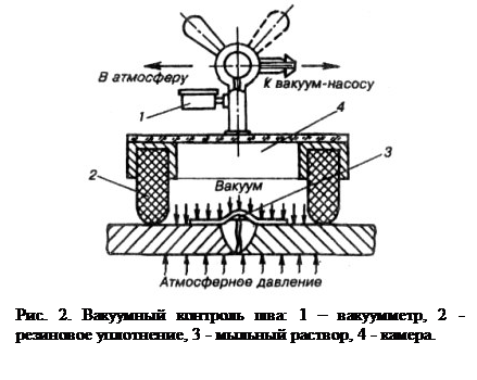
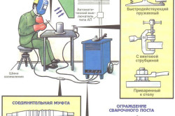
Vacuum control subjected to welds that cannot be tested with kerosene, air or water and which can be accessed only on one side. It is widely used in testing welds on the bottoms of tanks, gas holders, and other sheet structures. The essence of the method is to create a vacuum on one side of the monitored section of the weld and register on the same side of the seam the penetration of air through existing leaks. The control is carried out using a portable vacuum chamber, which is installed on the most accessible side of the welded joint, previously moistened with soapy water (Fig. 2).
Depending on the shape of the product being monitored and the type of connection, flat, angular and spherical vacuum chambers can be used. To create a vacuum, they use special vacuum pumps.
Fluorescent and ink control Also called capillary flaw detection, it is carried out using special fluids that are applied to the controlled surface of the product. These liquids, with great wetting ability, penetrate into the smallest surface defects - cracks, pores, lack of penetration. Luminescent control is based on the property of certain substances to glow under the influence of ultraviolet radiation. Before controlling the surface of the seam and the heat-affected zone, it is cleaned of slag and contaminants, a layer of penetrating liquid is applied to them, which is then removed and the product is dried. To detect defects, the surface is irradiated with ultraviolet radiation - in places of defects, traces of liquid are detected by glow.
Ink inspection consists in the fact that a wetting liquid is applied to the cleaned surface of the welded joint, which penetrates the cavity of defects under the action of capillary forces. After removing it, white paint is applied to the surface of the seam. Protruding traces of fluid indicate the location of the defects.
Monitoring by gas-electric leak detectors and used for testing critical welded structures, since such leak detectors are quite complex and expensive. They use helium as an indicator gas. With a high penetrating ability, it is able to pass through the smallest discontinuities in the metal and is recorded by a leak detector. In the control process, the weld is blown or the internal volume of the product is filled with a mixture of indicator gas with air. Penetrating gas through leaks is captured by a probe and analyzed in a leak detector.
The following control methods are used to detect hidden internal defects.
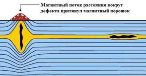
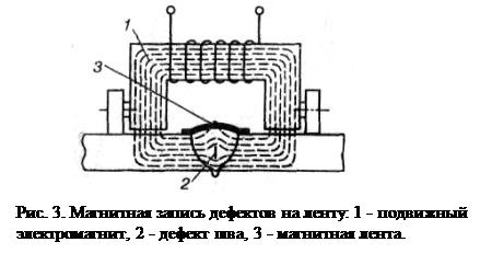
Magnetic control methods based on the detection of magnetic scattering fields formed in the places of defects during the magnetization of controlled products. The product is magnetized, closing the core of the electromagnet with it or placing it inside the solenoid. The required magnetic flux can also be created by passing current through the turns (3-6 turns) of the welding wire wound around the controlled part. Depending on the method for detecting scattering fluxes, the following methods of magnetic control are distinguished: magnetic powder method, induction and magnetographic. In the magnetic powder method, a magnetic powder (scale, iron filings) is applied to the surface of a magnetized compound in dry form (dry method) or a suspension of magnetic powder in a liquid (kerosene, soap solution, water — wet method). Accumulations of powder in the form of a correctly oriented magnetic spectrum will be created above the location of the defect. To facilitate the mobility of the powder, the product is slightly tapped. Using magnetic powder, cracks that are invisible to the naked eye, internal cracks at a depth of not more than 15 mm, metal stratification, as well as large pores, shells and slag inclusions at a depth of not more than 3-5 mm are detected. In the induction method, the magnetic flux in the product is induced by an alternating current electromagnet. Defects are detected using a finder, in the coil of which, under the influence of the scattering field, an EMF is induced, which causes an optical or sound signal on the indicator. In the magnetographic method (Fig. 3), the scattering field is fixed on an elastic magnetic tape tightly pressed to the surface of the joint. The record is reproduced on a magnetic flaw detector. As a result of comparing the controlled compound with the standard, a conclusion is made about the quality of the compound.
Radiation control methods are reliable and widespread control methods based on the ability of x-ray and gamma radiation to penetrate metal. The detection of defects by radiation methods is based on different absorption of x-ray or gamma radiation by metal sections with and without defects. Welded joints shine through special devices. A radiation source is placed on one side of the seam at some distance from it, and on the opposite side the cassette with sensitive film is pressed tightly (Fig. 4). When translucent, the rays pass through the welded joint and irradiate the film. In places where there are pores, slag inclusions, lack of fusion, large cracks, dark spots form on the film. The type and size of defects is determined by comparing the film with the reference images. X-ray sources are special devices (RUP-150-1, RUP-120-5-1, etc.).

X-ray inspection is advisable to identify defects in parts with a thickness of up to 60 mm. Along with radiography (exposure to film), fluoroscopy is also used, i.e. receiving a signal of defects during transmission of a metal onto a screen with a fluorescent coating. Existing defects in this case are viewed on the screen. This method can be combined with television devices and control is carried out at a distance.
When the welded joints are exposed to gamma radiation, the radiation source is radioactive isotopes: cobalt-60, thulium-170, iridium-192, etc. An ampoule with a radioactive isotope is placed in a lead container. The technology of performing transillumination is similar to x-ray translucency. Gamma radiation differs from X-ray in greater stiffness and shorter wavelength, so it can penetrate into the metal to a greater depth. It allows you to shine through the metal up to 300 mm thick. The disadvantages of gamma-ray transmission as compared to x-ray radiation are the lower sensitivity when thin metal is transmitted (less than 50 mm), the inability to control the radiation intensity, and the greater risk of gamma radiation during careless handling of gamma devices.
Ultrasonic testing based on the ability of ultrasonic waves to penetrate into the metal to a great depth and be reflected from the defective areas in it. In the process of control, a beam of ultrasonic vibrations from a vibrating probe plate (piezocrystal) is introduced into a controlled seam. When it encounters a defective area, an ultrasonic wave is reflected from it and captured by another probe plate, which converts ultrasonic vibrations into an electrical signal (Fig. 5).
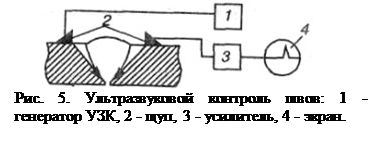
After amplification, these vibrations are applied to the screen of the cathode ray tube of the flaw detector, which indicate the presence of defects. The nature of the pulses is used to judge the extent of the defects and the depth of their occurrence. Ultrasonic testing can be carried out with unilateral access to the weld without removing the reinforcement and pre-treatment of the weld surface.
Ultrasonic monitoring has the following advantages: high sensitivity (1 - 2%), which allows to detect, measure and locate defects with an area of \u200b\u200b1 - 2 mm2; large penetrating power of ultrasonic waves, allowing you to control parts of large thickness; the ability to control welded joints with a one-sided approach; high performance and lack of bulky equipment. A significant drawback of ultrasonic testing is the difficulty in establishing the type of defect. This method is used both as the main type of control, and as a preliminary one, followed by transmission of the welded joints with x-ray or gamma radiation.
3. Control methods with the destruction of welded joints
These methods for controlling the quality of welded joints include mechanical tests, metallographic studies, and special tests in order to obtain the characteristics of welded joints. These tests are carried out on welded samples cut from the product or from specially welded control compounds - technological samples made in accordance with the requirements and technology for welding the product under conditions corresponding to the welding of the product.
The purpose of the tests is: assessment of the strength and reliability of welded joints and structures; quality assessment of the base and filler metal; assessment of the correctness of the selected technology; assessment of the qualifications of welders.
The properties of the welded joint are compared with the properties of the base metal. Results are considered unsatisfactory if they do not correspond to a given level.
Mechanical tests are carried out in accordance with GOST 6996-66, which provides the following types of tests for welded joints and weld metal: testing of the welded joint as a whole and the metal of its various sections (deposited metal, heat-affected zone, base metal) for static tension, statistical bending, impact bending, resistance to aging, measurement of hardness.
Control samples for mechanical tests carry out certain sizes and shapes.
Static tensile tests determine the strength of welded joints. The tests for static bending determine the ductility of the joint by the value of the bending angle until the formation of the first crack in the stretched zone. Static bending tests are carried out on samples with longitudinal and transverse seams with removed reinforcement of the seam flush with the base metal. Tests for impact bending, as well as rupture, determine the toughness of the welded joint. According to the results of determining hardness, structural changes and the degree of metal tingling during cooling after welding are judged.
The main task of metallographic studies is to establish the structure of the metal and the quality of the welded joint, to identify the presence and nature of defects. Metallographic studies include macro- and microstructural methods for the analysis of metals.
With the macrostructural method study macro sections and fractures of the metal with the naked eye or with a magnifier. Macroscopy allows you to determine the nature and location of visible defects in different zones of welded joints.
In microstructural analysis The metal structure is investigated at a magnification of 50 - 2000 times using optical microscopes. Microexamination allows you to establish the quality of the metal, including detecting burnout of the metal, the presence of oxides, clogging of the weld metal with non-metallic inclusions, the grain size of the metal, a change in its composition, microscopic cracks, pores and some other structural defects. The technique for manufacturing thin sections for metallographic studies consists in cutting samples from welded joints, grinding, polishing and etching the surface of the metal with special etchants. Metallographic studies are supplemented by measuring hardness and, if necessary, chemical analysis of the metal of the welded joints. Special tests are carried out in order to obtain the characteristics of welded joints, taking into account the operating conditions of welded structures: determination of corrosion resistance for structures operating in various aggressive environments; fatigue strength under cyclic loads; creep during operation at elevated temperatures, etc.
They also apply methods of control with the destruction of the product. During such tests, the ability of structures to withstand specified design loads is established and the destructive loads, i.e. actual margin of safety. When testing products with destruction, their loading scheme should correspond to the operating conditions of the product during operation. The number of products subjected to tests with destruction is established by technical conditions and depends on the degree of their responsibility, the system of organization of production and technological development of the design.
Destructive control methods include methods for testing control samples in order to obtain the necessary characteristics of a welded joint.
These methods can be applied both to control samples and to segments cut from the compound itself. As a result of destructive control methods, the correctness of the selected materials, the selected modes and technologies are checked, and the qualifications of the welder are evaluated.
Mechanical testing is one of the main methods of destructive testing. According to their data, it can be judged on the conformity of the basic material and the welded joint to the technical specifications and other standards stipulated by the industry.
Mechanical tests include:
- testing the welded joint as a whole in its various sections (deposited metal, base metal, heat-affected zone) for static (short-term) tension;
- static bending;
- shock bending (on incised samples);
- resistance to mechanical aging;
- measurement of the hardness of the metal in various areas of the welded joint.
Control samples for mechanical tests are cooked from the same metal, by the same method and by the same welder as the main product.
In exceptional cases, control samples are cut directly from the controlled product. Variants of samples for determining the mechanical properties of a welded joint are shown in Fig. 6.

Static stretching experiencing the strength of welded joints, yield strength, elongation and relative narrowing. Static bending is carried out to determine the ductility of the joint by the value of the bending angle until the formation of the first crack in the stretched zone. Static bending tests are carried out on samples with longitudinal and transverse seams with removed reinforcement of the seam flush with the base metal.
Shock bending - test determining the toughness of the welded joint. According to the results of determining the hardness, one can judge the strength characteristics, structural changes of the metal and the stability of welds against brittle fracture. Depending on the technical conditions, the product may be subjected to shock rupture.
Conclusion
It should be noted that among the listed control methods there is no one that would guarantee the identification of all welding defects. Each of these methods has its advantages and disadvantages. For example, when using radiation control methods, confidently detect volume defects of a small size (0.1 mm or more) and much worse - fusion, cracks and strained imperfections (~ 35-40%). The ultrasonic method, on the contrary, is more sensitive to planar defects and is ineffective when inspecting structures with defects in the form of pores of 1 mm or less in size. To detect surface defects, either capillary or magnetic control methods are used.
Practice shows that the correct organization of control processes, as well as the skillful application of one method or another or a combination of methods in control, make it possible to evaluate the quality of welded joints with great reliability.
And to eliminate defects in welds, the following methods are used:
The incompleteness of the seams is eliminated by surfacing an additional layer of metal. In this case, the surfaced surface must be thoroughly cleaned to a metallic luster with an abrasive tool or a metal brush. Excessive reinforcement of the seam is eliminated with an abrasive tool or a pneumatic chisel. Lack of penetration, craters, porosity and non-metallic inclusions are eliminated by cutting out with a pneumatic chisel or by cleaning with an abrasive tool the entire defective area with subsequent welding. Often used smelting of the defective area with a cutter surface oxygen or air-arc cutting. Undercuts are brewed with thin roll seams. Nodules are eliminated by treatment with an abrasive tool or with a pneumatic chisel. External cracks are eliminated by cutting and subsequent welding. To prevent the propagation of a crack at its ends, holes are drilled. Crack cutting is performed with a chisel or a cutter. Edging edges are cleaned of slag, metal spray, scale and brew. Seams with internal cracks are cut down and welded again. If there is a network of cracks, the defective area is cut out and a patch is applied instead of welding.
List of sources used
1. Defects and quality control of welded joints http://www.shtorm-its.ru/eng/info/svartech/w23.php
2. Weld quality control http://www.elfplast.ru/welding/quality/
3. Quality control of welding works. Http://www.biysk.ru/~zimin/00100/00085.html
4. Destructive testing methods for welded joints http://www.techno-sv.ru/kontrol-svarki2.html
The quality of the weld directly affects the reliability of the entire element, it is especially important for parts experiencing increased or bearing loads. Therefore, for quality control, after the main work, an inspection is carried out in order to identify defects. There are many diagnostic methods that are divided into
- destructive
- non-destructive.
The former imply a mechanical or other effect on the weld, in order to identify its errors. In this case, part or all of the welded section loses its structural properties.
For this reason, non-destructive methods for monitoring welds are considered more popular and appropriate, which we will consider further.
Currently, the following non-destructive methods are distinguished:
- visual inspection;
- radiation method;
- magnetic research;
- ultrasound method;
- capillary method;
- permeability control.
Visual inspection
Any quality control of welded joints begins with a simple external inspection. This is enough to determine both external and internal gaps, plus there is no need to use non-destructive testing equipment. For example, different seam heights may indicate a lack of penetration in different areas. Before inspection, the seams are cleaned from technological pollution, namely, slag, scale and metal spray.
Visual inspection of the weld
So that minor flaws become more visible, the surface is treated with an alcohol solution, and then with a 10% solution of nitric acid. After this procedure, the surface will become dull and show pores and cracks.
The main thing is not to forget to clean the acid with alcohol after troubleshooting the seam.
Inspection is the main way to identify geometric deviations, such as pores, cracks, sagging, undercuts. It is possible to carry out this test item with better quality using additional instruments.
To do this, it is best to use a magnifier, as well as better lighting, preferably with a mobile light source. A magnifying glass will detect cracks and pores hidden to the eye, as well as trace their path. To control the width of the rollers, you can use measuring instruments, such as a ruler or vernier caliper.

Visual Measuring Instruments
Radiation flaw detection
The radiographic method for controlling welded joints exists in two variations:
- x-ray radiation;
- gamma radiation.
The simplest of the presented methods to detect weld errors is to enlighten the product with x-rays. They have the property of penetrating through metal objects, while acting on the film. Thus, the resulting image is a direct map of most of the defects. Using penetrating rays, slag inclusions, gas pores, edge displacements, burns and other gaps are revealed.

X-ray slag inclusions
Before starting work, the investigated area and the adjacent plane must be properly cleaned. To do this, remove slag, spray, scale and other flaws. Also, before transillumination, an inspection is mandatory and, if low-quality areas are identified, they should be eliminated.
It is forbidden to start scanning in the presence of external defects, since the procedure is designed to diagnose and detect hidden defects.
If errors are found, the decision on the tolerance or alteration of a particular part lies with the regulatory documentation. It is the established rules and instructions that allow us to determine the occurrence of errors in the standards established for this product. 
For the procedure, the x-ray tube is positioned so that the beam hits the seam at right angles. On the other side of the product is an X-ray film cassette. Since existing defects affect the permeability of X-rays less, they will be visible as darker areas on the film. An x-ray test lasts depending on - film quality, thickness and focus. After the film appears and you can see the result of welding.
When radiographic control does not reveal:
- any discontinuities and inclusions with a size in the direction of transmission less than twice the sensitivity of control;
- lack of penetration and cracks, the opening plane of which does not coincide with the direction of transmission;
- any discontinuities and inclusions, if their images on the pictures coincide with images of foreign parts, sharp angles or sudden changes in cracks of the translucent metal.
Gamma - radiation by the principle of operation is practically no different from x-ray. These are radioactive rays that can penetrate metal and react to its unevenness. In this way, I inspect from 10 to 25% of all seams, if the design is responsible, then all seams.
As a radiation source, various chemical elements suitable for certain metals are used:
- Cobalt - 60 (steel, cast iron, copper, bronze and brass up to 25 cm thick), due to hard penetration, the element is suitable for most steels and large thicknesses;
- Cesium - 137 (steel up to 10 cm);
- Iridium-192 (steel up to 5 cm, aluminum up to 10 cm);
- Thulium-170 (steel and aluminum up to 20 cm).
With a decrease in permeability, the appearance of the alloys and their thickness decreases, but the average image quality remains and allows you to determine the main defects.
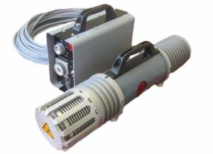
Portable x-ray device MART-250
Unlike x-rays, gamma rays have several advantages:
- isotopes remain operational for a long time;
- lighter equipment;
- the possibility of troubleshooting complex nodes;
- increased permeability of rays;
Important! Both types of radiation are extremely dangerous to humans. That is why access to work can only be with specially trained employees dressed in a full set of protective equipment. The place of basing and operation of the penetrating equipment must also be protected; for these purposes, lead plates, screens and other means are used.
Magnetic flaw detection
Such control of welded joints is based on the property of magnetic lines of force to respond to changes in the thickness of the metal. By fixing such deviations with special instruments, it is possible to find errors with high accuracy in the thickness and on the upper part of the alloys.

At the moment, there are three variations of the method:
- magnetic powder;
- magnetic induction;
- magnetic graphic.
Powder coating consists in the fact that going over the joint of a seam, a dry powder or emulsion is applied, then the alloy is magnetized and inaccuracies are determined. If the "dry method" is taken, then iron oxide or oxides acts as a powder. Magnetize the product with an electromagnet, a solenoid, or supply current to the product. After, gently tapping with a hammer, give the powder
the opportunity to take your position. Excesses are removed by a stream of air and then flaws are fixed. The last step is demagnetization.
In the wet method, magnetic powder is mixed with kerosene or special oil. The resulting suspension is applied to the seam, and its mobility, dispersion or accumulation of powder are direct identifiers of errors.
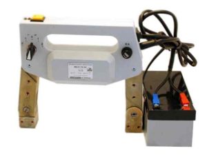
Magnetic flaw detector
In the induction method, all data is recorded by an induction coil. Special devices - flaw detectors, fix magnetic dispersion in metals up to 25 mm thick.
Graphic consists in fixing magnetic fluxes on a special tape. It is mounted along the seam, and then the deviations are determined on the screen of the cathode ray tube.
Magnetic methods are suitable exclusively for ferromagnetic alloys; other metals cannot be investigated in this way.
Ultrasonic inspection method
Along with the previous method, ultrasonic flaw detection makes it possible to fix the deviations generated by the reflection of waves from the boundaries of media with different properties. 
An ultrasonic source sends a signal that is reflected when it reaches the end of the alloy. If a signal meets a defect in its path, then this is reflected in the wave, which in turn is detected by the device. Various defects have their own reflections; therefore, it is quite simple to determine the nature of a flaw.

Ultrasonic Flaw Detector
Of the methods already described, this is considered the most convenient for use. This is due to the ability to determine the flaw both on the surface and in the depth of the metal. Also, the method does not have such strict limitations as magnetic. There are a number of metals with large grains, such as cast iron, which are not amenable to ultrasound, but for all other alloys it is easy to control the quality of welding.
There is another drawback - the complexity of decoding the received data. Alas, flaw detectors give the user very specific data that should be decrypted. Without preliminary preparation, it is practically impossible to do this, so a trained specialist is needed for the work.
Capillary flaw detection
This method is based on the properties of liquids with low surface tension. Such liquids do not collect in large drops in one place and tend to drain, but at the same time they are able to fill the smallest grooves and holes. Similarly, surface defects and, in rare cases, through channels are determined.

Capillary flaw detection
A special solution is applied to the seam, which instantly fills all the grooves, pores and other minor defects. Then, examining the seam, you can find large flaws. For greater convenience, liquids are tinted with a dye, luminescent and other coloring additives are added.
Permeability welding quality control
The method is a logical continuation of the capillary. The basic idea is that using fluids with deep penetration properties, you can define the through ditches of the seam.
To do this, take simple kerosene, apply on one side of the seam, and on the other fix wet spots, signaling through channels. Among the shortcomings, it is worth noting the need for thoroughly cleaning the surface and maintaining accuracy at all stages to exclude accidental contamination of the opposite side of the weld.
Conclusion
Welding and quality control of welded joints of metal structures are inextricable parts of one process. It doesn’t matter whether work is carried out at home or in production, without a proper strength test the product cannot continue to exist. The methods described above will allow you to check the quality of welded joints without breaking the seam.