The gas distribution system is a complex of interconnected facilities, the main purpose of which is to supply “blue fuel” to the consumer. When assembling such networks, of course, all the required technologies must be followed. Laying a gas pipeline is a responsible matter, and safety should not be neglected when performing such work in any case.
The main components of the gas pipeline
Networks designed to transport “blue fuel” include:
- external highways of settlements;
- means of electrochemical protection;
- regulatory points;
- automated control systems;
- internal highways.
External gas pipelines are pipes stretched outside buildings to the case or disconnecting device when entering the premises. An internal system is pipes laid from an external structure to consumers (stove, boiler). Methods for laying a gas pipeline can be different.
Types of systems
There are classified the lines designed for the supply of "blue fuel", according to several criteria:
- type of gas (LPG, natural);
- the number of pressure control stages (single or multi-stage);
- designs (deadlock, ring, mixed).
In settlements for use by owners of houses and apartments, mainly natural gas is supplied. LPG (liquefied) on highways is rarely transported. In most cases, it is pumped into cylinders. LPG is supplied through pipes only if there is a tank unit or regasification station in the village.
In cities and large towns, a multi-stage distribution gas pipeline is usually laid. Assembling a single-stage low pressure is very expensive. Therefore, it is advisable to install such systems only in small villages. When assembling multi-stage gas pipelines, regulatory points are established between branches of different pressures.
Actions before laying
Before proceeding with the assembly of the gas pipeline:
- calculate the required amount in a particular locality of gas;
- determined with the diameter of the pipes;
- determined with the need to install automated control systems;
- make up the project of an external gas pipeline.
Consumers are usually responsible for assembling the internal gas supply systems. The boilers and stoves are connected by agreement with the owner of the house, licensed companies of the corresponding specialization.
Calculation of the required gas
Such planning takes into account:
- population and building density;
- lack or availability of hot water.
Calculate the estimated maximum values. For example, for settlements with the number of people living from 700 to 2000 and a building density of 150-960 m 2 / ha, this figure will be 0.7-1.6 m 3 (h · people). In the absence of hot water, the estimated maximum flow rate is reduced by 25%. They carry out the calculation taking into account the prospects for the development of a village or city for 10 years in advance.
Pipe calculation
The required diameter of the external gas pipelines is selected based on:
- estimated consumption of "blue fuel" during hours of maximum consumption;
- pressure loss in the line.
Preliminary diameter calculations are performed according to the formula
d \u003d 3.62 * 10 -2 √ Q h (273 + t) / P m v,
where Q h - hourly flow rate at normal pressure, P m - absolute pressure in the area, v - gas velocity.
Subsequently, adjustments are made to the results obtained depending on the resistance in the line (fittings, connections, turns). To determine the pressure drop, special formulas are used (for each gas supply mode - its own).
Installation of external gas pipelines: automated control systems
Such equipment is designed to provide the highest performance lines. Automated WGs) have a centralized structure. Their main elements are:
- controlled points (KP) installed on external highways;
- central control room (upper level).
- gas distribution systems (lower level).
The central control center includes several workplaces united by means of computer networks.The automated control systems of gas pipelines are used:
- for the purpose of operational control of distribution;
- equipment condition monitoring;
- accounting for gas intake and consumption.
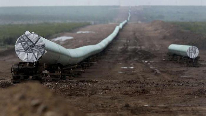
How can highways be laid?
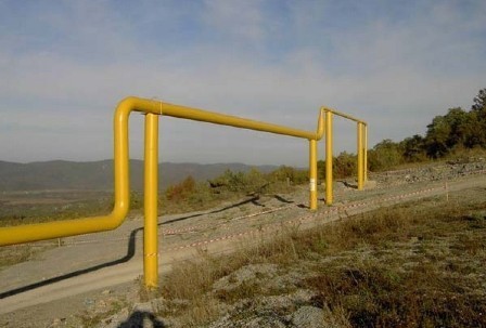
It is allowed to pull the gas pipeline underground or above ground. The latest technology is the most economical. The method of laying underground is considered safer. This is how gas pipelines are usually pulled through settlements. However, the implementation of such a technique is more expensive. In servicesimilar the highway is also more costly.
Some sections of the network in large settlements can also be laid above the ground.But they are almost never too long.Overhead gas pipelineprovided for and on the territory of industrial enterprises.
Before n by the beginning of the installation of the network, its scheme is mandatory. The highway project, according to the standards, must be implemented in a topographic plan.
Underground gas pipeline construction: rules
On-site assembly of the gas pipeline is carried out in compliance with the following standards:
- the distance between the gas pipeline and other ground communications should not be less than 0.2 m;
- at the intersection with the communication manifolds, the pipes extend in a case;
- gas pipelines are laid above other engineering systems;
- cases beyond the intersection are displayed at a distance of at least 2 m;
- the ends of the cases are sealed with waterproofing materials.
Depth of gas pipeline laying dit should be at least 0.8 m according to the standards. But as a rule, trenches under such systems are dug up one or more meters. In any case, the laying depth should be such that the temperature of the pipe wall does not fall below 15 degrees.
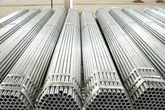
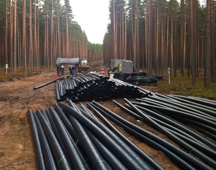
Pipe requirements
Blue fuel can be supplied in underground systems via steel or polyethylene highways. The advantage of the latter is corrosion resistance andt relatively low cost. Howeveruse polyethylene pipes for transportation "blue fuel " standards do not always allow. For example,underground gas pipelines using such material is not possible:
- on the territory of settlements with a gas pressure of more than 0.3 MPa;
- beyond the territory of settlements at a pressure of more than 0.6 MPa;
- for the liquid phase of SSU;
- when the wall temperature of the pipeline is below 15 degrees.
The strength factor of pipes used for laying gas outdoor networks should be at least 2.
Steel gas pipes can be both seamless and welded. For the underground system, similar highways with a wall thickness of at least 3 mm can be used. It is allowed to use both straight-line pipes and with a spiral seam for gas transportation.
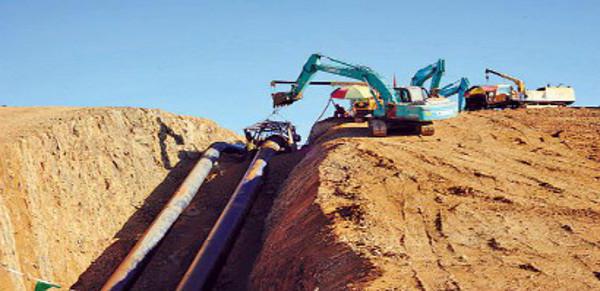
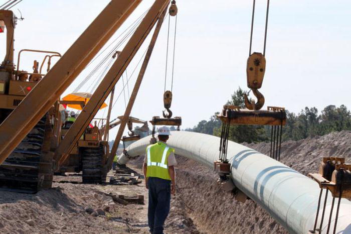
Underground trunking technology
Such systems are assembled as follows:
- marking of the construction strip and geodetic breakdown of horizontal and vertical corners of turns;
- earthworks are carried out with a single-bucket excavator with a backhoe;
- manual completion of the trench;
- the bottom of the trench is leveled;
- just before laying, pipes are delivered to the site;
- pipes are inspected in order to detect defects;
- the lashes are laid in a trench;
- welding and joining works are performed;
- gas pipeline tests are being carried out;
- backfilling of the trench is being carried out.
Preparing a trench for laying a gas pipeline in advance with standards is not allowed. There should not be any stones and debris at its bottom. Pipes are welded in a whip outside the trench. This eliminates the possibility of leaks in the future. When lowering the lashes, they must not be allowed to hit the bottom and walls.
The assembly of gas pipelines in the winter season is allowed by standards. However, in this case, the trench should be dug up to unfrozen soil. On rocky sections, pipes are laid on a sand cushion. The thickness of the latter should be approximately 200 mm. This eliminates the risk of damage to the pipes due to contact with stones.
special instructions
Sometimes gas pipelines have to be pulled along problem areas. On landslide territories, as well as on soils subject to erosion, construction must be carried out below the boundary of possible destruction. Pipes pull at least 0.5 meters from the level of the sliding mirror.
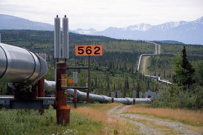
Rules for the assembly of elevated systems
Gas pipeline requirements of this type, the following:
- above the ground, the gas pipeline should be located not lower than 2.2 m in the places of passage of people, 5 m - above the roads, 7.1 m - over the tram tracks, 7.3 m - in those places where trolleybuses travel;
- distance between still line supports should be equal to a maximum of 100m with a pipe diameter of up to 30 cm, 200 m - up to 60 cm, 300 m - over 60 cm; designed for laying above the ground, must have a wall thickness of at least 2 mm.
M distribution gas pipelines in small towns are often laid along supports. The distance between the latter directly depends on the diameter of the pipes. So, for Du-20, this indicator will be 2.5 m, Du-50 - 3.5 m, Du-100 - 7 m, etc.
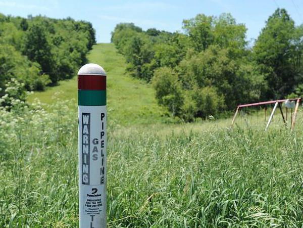
What is a gas protection zone
Engineering systems of this variety - facilities explosive. Therefore, in the immediate vicinity of them, no construction should be carried out. The sizes of security zones depend on the types of gas pipelines:
- high pressure category I (0.6-1.2 MPa) - 10 meters;
- high pressure category II (0.3-0.6 MPa) - 7 m;
- medium pressure (5-300 MPa) - 4 m;
- low pressure (up to 5 MPa) - 2 m.
Gas protection zoneLPG is usually equal 100 meters.
According to the standards, once a year the route is adjusted with the introduction of existing changes to the documentation.In order to mark the protection zone of the pipeline, special columns are used. Their location is prescribed at a distance of not more than 50 m from each other. Are indicated by columns and places of turn of the highway. At intersections with roads and bridges in the security zone, appropriate warning signs are installed. On the highway in such places signs are also provided prohibiting parking.
Laying gas pipelines indoors
In this case, certain safety standards must also be observed.Is produced gas pipeline transit inside buildingsabout external surfaces of walls at least 1.5 meters above the floor. Sometimes pipes are pulled in channels covered by shields. The latter at the same time, according to the regulations, should be easily removable.Through the walls or floors, gas pipelines are laid in metal sleeves insulated with non-combustible material.
According to the regulations, it is forbidden to pull pipes:
- on door and window frames;
- transoms;
- platbands.
Wooden walls before installing gas equipment next to them should be insulated with asbestos-cement sheets. All joints of the internal gas pipeline are welded. It is allowed to make detachable only connections in places of installation of shutoff valves.
Steel pipes are commonly used to assemble internal systems. But sometimes copper is also used for this purpose. It is not allowed to use such highways only for transporting LPG.
Internal connectiontransit the gas pipeline to the external one and its assembly should be carried out by standards only by specialists of a licensed company. After the installation of the system, its tests and acceptance are carried out with the signing of the corresponding document.
The construction company "BOSS" provides services to legal entities and individuals for the laying and repair of gas pipelines. We guarantee quality and compliance with standards, since during design and installation all norms and requirements of GOST and SNiP are taken into account.
Types of pipelines by purpose and pressure
When compiling project documentation, the direction and conditions of the use of pipes must be taken into account: intra-quarter, courtyard, street or inter-workshop. Safe operation and uninterrupted operation largely depend on pipes that are selected taking into account pressure (low, medium or high).
When constructing a gas pipeline, several categories of pipeline are distinguished:
1.IV - low pressure, the total load should not exceed 5 kPa. The main purpose is to supply gas to residential facilities; steel and polyethylene pipes are used during installation.
2.III - medium pressure. Pipes are designed for a load in the range from 5 KPa to 0.3 MPa. The pipeline is designed to transport media to distribution points.
3.II - high pressure. It is allowed to lay a gas pipeline of both steel and HDPE pipes in distribution areas to residential premises and industrial facilities with a network pressure in the range of 0.3-0.6 MPa.
4.I - high pressure. The pipeline is designed for a load of 0.6-1.2 MPa and is designed to transport media to distribution areas.
5.I-A - high pressure. When laying, a gas pipeline is used from steel or polyethylene pipes, designed for a network pressure of not more than 1.2 MPa for connecting different stations. It should be understood that the construction of a gas pipeline is a big responsibility, since if the design and installation standards are not followed, the danger to surrounding objects and people increases.
The gas pipeline can be laid above or below ground; the pipeline is also classified according to its purpose:
inter-settlement - networks are laid out beyond the boundaries of cottage villages and cities;
introductory - engineering communications section from disconnecting equipment to the internal pipeline;
gas distribution pipelines are installed outside;
internal - the network gap from the introductory part to the final consumer.
Our company employs qualified engineers, welders and fitters with tolerances. All this allows us to carry out the construction of gas pipelines in urban areas, to office buildings, settlements and industrial facilities.
Features of the construction of an underground gas pipeline
Due to the high level of safety, the underground laying of the gas pipeline is used much more often than overhead installation, since engineering networks are protected from the influence of the human factor, climatic influences and mechanical stresses. But here it is also required to observe certain rules on the depth of the pipeline in view of the load from the roadway and the effects of precipitation. Soil composition and soil freezing are also taken into account. In underground gas pipeline construction, steel with insulation and polyethylene (HDPE) pipes are used, which avoids the formation of corrosion. HDPE and steel pipes can be combined, since the entrance to the building in most cases is carried out by a steel pipeline. With the integral connection "polyethylene-steel" the distance from the foundation of the building to the communications should be at least 2 meters with a medium pressure gas and 1 meter with a low pressure gas.
Consider the requirements for the depth of communications, taking into account the direction of use:
if laying is planned for concrete or asphalt, then the depth should be at least 0.8 m, if there is no hard coating - at least 0.9 m;
if there is no movement of cars and heavy special equipment on the site, the laying depth can be reduced to 0.6 m;
for transporting dry gas, it is possible to lay a gas pipeline to a depth of 1.2 m.
During the reconstruction, installation and repair of the gas pipeline, we take all safety measures and are guided by regulatory documents PB 12-529-03. A prerequisite is the installation of a signal tape, which further simplifies the maintenance process and warns of the presence of a pipeline with gas. That is, during construction on the site, the excavator receives a clear signal that further excavation is strictly prohibited and dangerous. High-strength polyethylene is used as a material for manufacturing the signal tape, which guarantees a long service life. Features of laying an overhead gas pipeline The technology for constructing a gas pipeline (aboveground or underground) is selected at the design documentation development stage.
Overhead installation is most often used under the following conditions:
highly branched underground utilities;
dense urban development;
the presence of bumps and various obstacles in the form of ponds, ravines, etc .;
at industrial and commercial facilities.
When organizing the above-ground network, steel pipes are used. The method is characterized by minimal costs for material, work, maintenance and repair of the gas pipeline. But there is a high probability of mechanical damage and this factor needs to be given special attention when developing a project. When attaching the pipeline to houses and buildings, the walls should have certain fire resistance indicators - I-IV degree, and ceilings - I and II degrees. Branched sections and shutoff valves are mounted on specialized supports. When constructing a gas pipeline in accordance with regulatory documents, the minimum height from the soil surface is 35 cm. If the installation is planned to be carried out in places with a large crowd of people, then the height is not less than 2.2 m, and on the highway and motor vehicle routes - 4.5 m, above Railway communication - 5.6-7.3 m.
When reconstructing, servicing, laying and repairing an elevated type gas pipeline, we comply with the full list of requirements:
flange joints are removed at least 40 cm from supports and walls;
when securing communications to the walls of buildings, pipes are used with a design load of up to 0.3 MPa; welds in the pipeline from d to 20 cm are made at least 30 cm from the walls of the object;
when coordinating project documentation with the appropriate authorities, in certain cases it is allowed to lay the gas pipeline on one support with other engineering networks;
the minimum distance from the supports to the roadway should be at least 10 m;
construction of a gas pipeline of aboveground and underground type is allowed at industrial facilities, but it is better to give preference to the second option due to a higher level of security.
When contacting our BOSS company, you can always get expert advice on laying a gas pipeline, and also order a preliminary estimate for free. Working with professionals is always profitable and safe!
When installing gas pipelines, the following basic requirements should be observed:
1) the position of the gas pipeline in the plan and profile must comply with the design;
2) on the gas pipe laid in the trench (or laid above ground) the insulation of the pipe surface must be preserved;
3) butt and other pipe joints must be durable and tight;
4) the gas pipeline must fit snugly against the natural or artificial base of the trench;
5) the bed under the gas pipeline after laying should be kept;
6) distances must be maintained between the gas pipeline and the crossed underground structures in accordance with the norms.
A trench under the gas pipeline is prepared immediately before laying. The bottom is planned and cleaned of debris, dirt, stones and other items.
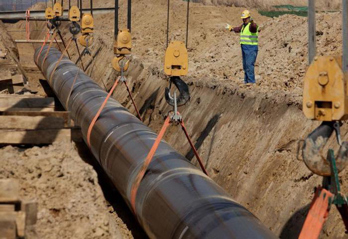
The gas pipeline is laid on a natural or artificial foundation with lashes or sections from separate pipes welded on the edge of the trench. Before lowering the lashes or sections into the trench, they are cleaned of dirt and scale from the inside, the ends of the sections or lashes are closed with inventory corks, protecting the pipes from clogging.
Lowering (or other movement of the gas pipeline) is carried out using inventory soft "towels" that do not violate the integrity of the anti-corrosion insulation. Scourges or sections are lowered smoothly, without jerking, striking the walls or the bottom of the trench, without sharp bends of the gas pipeline in the vertical or horizontal planes.
In winter, the gas pipeline is laid on an unfrozen foundation immediately after opening the trench. If the gas pipeline is laid on a frozen base in soils that are not prone to heaving, they are backfilled with fine sandy soil with a thickness of at least 100 mm.
Under a gas pipeline laid in rocky and rocky soils, they add a bed of soft local or sandy soil with a thickness of at least 200 mm.
The pits for welding fixed joints of the gas pipeline, the installation of condensate traps, hydraulic locks and other network devices are torn off immediately before installation. Pits are filled up after testing the gas pipeline for strength and checking the state of its insulation.
Installation of gas pipelines is performed in this sequence: develop trenches and pits, arranging, if required, drainage; clean the bottom and walls of trenches and pits; dig pits in places of welding pipes and insulation joints; arrange a natural or artificial foundation for the pipeline; perform bottoms of wells and chambers; lower the pipes into the trench, laying them on the base; weld pipes, mounting fittings and fittings; they knock down and sprinkle the pipeline with soil (except for joints); erect walls and ceilings of wells and chambers; purge the pipeline with a fan; pre-testing the pipeline for strength, checking the quality of welds and flange joints; isolate joints; fall asleep the pipeline; finally test the pipeline after completion of construction works.
In urban conditions, when it is impossible to keep an open trench of long length for a long time, pipelines are mounted in small areas - grips. They dig a trench with a length equal to the length of the grapple. In this case, the length of the lash is equal to the length of the gripper. Pipes are collected and welded in a scourge outside the trench along the edge, and then the lashes are lowered to the bottom of the trench by jib cranes or pipe layers.
For short grips, it is advisable to install the pipeline using vehicles (installation "from the wheels"). Scourges with a length of 25-35 m (for the grip size), prepared in the factory and brought to the construction site by cars with a special trailer, are laid by taps directly from the vehicles in trenches.
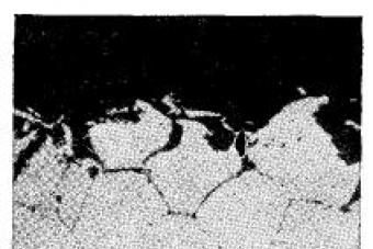
Waterproofing of steel pipelines. Steel pipelines laid in the ground are susceptible to corrosion due to exposure to the surrounding soil. As a result of the effects of soil corrosion and corrosion caused by stray currents, pipe walls can quickly collapse to their entire thickness in a relatively short time.
There are various ways to protect pipe metal from corrosion.. One of the main methods of protection is coating the external surfaces of pipelines with anticorrosive materials. The protective coating must be waterproof, fit tightly to the pipes, be an insulator from electric currents, durable, able to withstand mechanical stresses (when backfilling trenches and linear temperature deformations of the pipeline) and at the same time be flexible, able to crack and not soften to runoff with temperature fluctuations.
Corrosion-resistant coating of steel pipe surfaces they are mainly performed at the factory, and insulation is applied at the construction site only at the joints of welded pipelines that have passed hydraulic or pneumatic tests for density and strength, or they can fix possible insulation damage during pipe transportation or installation. Since insulation restoration at the construction site is difficult, it is especially important to handle insulated pipes from the moment they are loaded at the factory until they are laid in the trench, bearing in mind, moreover, that the bitumen insulation layers do not have significant mechanical strength.
Corrosion-resistant coatings are based on bitumen, polymeric materials, etc.. Widely shelter as protective coatings bituminous mastics. In addition to mastics, the composition of the insulation coating includes roll insulation materials (polymeric) and wrapping materials (kraft paper).
Depending on the corrosion characteristics of the soils into which the gas pipeline is laid, the type of insulation is determined: normal, reinforced, very reinforced.
The primer is a mixture of gasoline and bitumen in a ratio of 1: 1.25 by weight or 1: 3 by volume; the primer is manufactured at the factory and delivered to the construction site in airtight containers.
The primer is applied to the pipe surface previously cleaned of scale, dirt and rust..
Pipes are cleaned mechanically: electric and pneumatic brushes, scrapers, sandblasting machines or manually brushes to a metallic luster (monotonous steel color). Good pipe surface cleaning is a guarantee of high quality anti-corrosion coating.
The primer should be even, without gaps, clots, smudges and bubbles.
Mastic in the conditions of the construction site is prepared in special bitumen boilers and applied hot (temperature not lower than 170 ° C) onto a dry primer layer using a watering can, rubbing the mastic from the bottom of the pipe with a towel.
The joints are wrapped with brisol and kraft paper on a hot layer of mastic with an overlap of turns of 20-30 mm. The inner layers can be done without overlap. The winding should fit snugly without any voids or creases.
Installing a lens compensator. The lens compensator is mounted in the well after installing the valve, and then it is connected to the gas pipeline.
The compensator is inspected before installation (the compensator to be installed must not be deformed) and the composition indicated in the passport is poured into the lower part of the compensator.
Before installation, the compensator is either stretched (at a negative outside temperature), or compressed (at a positive outside temperature). After installing the compensator in the working position, the nuts on the rods are pushed back by an amount that ensures its full compensating ability in accordance with the passport data.
The design of the wells can be prefabricated or monolithic, but in any case, the wells must be waterproof. To ensure the water resistance of wells in soils, waterproofing is used. To do this, the external walls are glued with borulin or plastered with waterproof cement to a height of 0.5 m above the maximum groundwater level.
Prefabricated elements of wells are connected on cement mortar with grouting. During the construction of brick wells, masonry seams from the inside are embroidered and rubbed with cement mortar.
Before laying the gas pipeline in the trench, bottoms of the wells are arranged, and after laying the pipes and mounting the fittings, walls and ceilings of the wells are constructed. If a pit for collecting water is provided at the bottom of the well, the slope to it must be at least 0.03. Sinuses of wells after filling with sandy soil are watered and compacted layer by layer.
Condensate collectors designed to collect and subsequently remove condensate from the gas pipeline, as well as to remove moisture that has got into it during construction, during flushing, etc., is installed at the lower points of the gas pipeline (low, medium and high pressure). Water from gas pipelines flows into condensate collectors by gravity. Periodically, water is removed through special pipes, which are also used to purge gas pipelines and release gas during repair of gas supply networks. The dimensions and designs of the condensate traps depend on the gas pressure and the amount of condensing moisture.
Condensate collectors are delivered to the facility coated with anti-corrosion insulation. The condensate collector must have a number welded onto the body and be accompanied by a passport confirming its compliance with the standards and requirements of the technical conditions for its manufacture and testing.
An electrode is welded to the tube of the condensate collector installed in the places of propagation of stray currents to measure the potential difference between the ground and the pipeline. A ground electrode is installed in the ground near the condensation tube.
Gate valves with a diameter of 50 mm and more are used as stop valves in gas pipelines of all pressures. Using valves also regulate the flow of gas. Gate valves are used cast iron and steel. Parallel gate valves are installed on gas pipelines with a pressure of 3 kgf / cm2, and wedge valves are installed on gas pipelines of other pressures.
Gate valves on gas pipelines of large diameters are equipped with a worm gear reducer, pneumatic, hydraulic or electric actuator. To equalize the pressure, a bypass pipe is mounted on both sides of the gate valve, which makes it easier to lift the shutter.
When installing the valve in the well, it must be taken into account that there must be free access to it.
Bronze, cast-iron, steel taps with a nominal diameter of 15 to 700 mm are used in underground and elevated gas pipelines as disconnecting devices. Cranes can be coupling and flange. Cranes are used, as a rule, with a lubricant, which ensures their tightness, corrosion resistance, and also reduces wear on sealing surfaces and facilitates the rotation of the plug.
Hydraulic locks used as disconnecting devices on low pressure gas networks. To turn off the gas at the entrance to the building, water is supplied to the hydraulic lock through the tube. Having filled the lower part of the hydraulic lock, the water interrupts the flow of gas through the hydraulic lock and the consumer switches off. For the subsequent start-up of gas, water from the hydraulic lock is removed by purging.
At the factory, hydraulic locks are tested for strength and density, which is noted in his passport. Its surface, including a tube for water inlet, is covered with waterproofing.
Install a water seal on dense soil or sand preparation strictly vertically along a plumb line. The water trap tube, as well as the ground electrode, is led out under the carpet. Hydraulic locks are equipped with devices for measuring the potential difference between the gas pipeline and the ground.
Compensators are used to relieve stress in a gas pipeline during its linear measurements. - lengthening or shortening as a result of temperature fluctuations of the soil or changes in the temperature of the gas passing through the pipeline. Designs of compensators are various. The lens compensator, which can be single-flange or double-flange, is connected to the gas pipeline by welding or on flanges.
You might also be interested in:Yard gas wiring. From the street distribution gas pipeline arrange a gas input into the home. At the gas inlet, a valve is installed at a distance of at least 2 m from the wall of the building or fence. From the input, a yard gas wiring is laid with inputs to the stairwells of buildings.
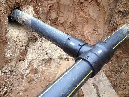
The input is connected to the street gas line using a tee or a steel pipe welded into the network, and only in some cases - with the help of saddles.
Entering into the territory of the construction site and gas pipelines in the yard is arranged from steel pipes laid in the ground at the same depth as the street network of the gas pipeline. The diameters of the inlets are determined depending on how much gas is consumed. The smallest diameter is 50 mm. Pipes are laid with a slope of at least 0.003 towards the outer line.
The distance between the pipes of the gas network and the mains of the water supply system, heating system, sewage system in the vertical direction must be at least 0.15 m, and between the gas pipelines and electric and telephone cables - at least 0.5 m.
A parallel valve on the gas inlet is installed directly in the ground or in a metal casing. The spindle head of the valve is brought to a level with a coating of the yard and placed in a metal cap. To protect the spindle from damage, a case from the pipe is put on it.
Gas pipelines from steel pipes laid in the ground must first be coated with insulation to protect them from corrosion.
Separate sections of the pipeline are connected by welding. After pressure testing of the gas pipeline, the places of welded joints are isolated directly in the trench.
Intra-house gas pipeline network. Gas pipelines should be commissioned in residential and public buildings in non-residential premises accessible for inspection of gas pipelines (stairwells, kitchens, corridors).
Gas pipelines may be laid in technical corridors and technical undergrounds.
In these cases, technical corridors and undergrounds must meet the following basic requirements: - the height of the premises must be at least 1.6 g and the width of the free passage at least 1 m. The premises must have natural, supply and exhaust ventilation, providing at least one air exchange in hour; - technical corridors and technical undergrounds are not allowed to be used for storage facilities. They must have at least two entrances from the outside, not communicating with the entrances to the living quarters, and a gas-tight ceiling; gas passage passages must be sealed.
Pipelines running in technical corridors and undergrounds are welded; installation of stop valves is prohibited. In this case, cranes are installed in the premises of the first floor.
When laying a gas pipeline with other communications, it must be located below other pipelines or at the same level with them, and the relative position should be such that it is convenient to inspect and repair them.
Laying risers and the internal network of the gas pipeline in living rooms is not allowed.
Gas risers are mounted from un galvanized steel water-gas pipes on a thread or on welding. When passing through the floors, the risers are laid in sleeves from scraps of pipes of larger diameter, which are installed with the lower end in a level with the ceiling. The liners should protrude 50 mm above the floor so that water does not flow into the liner when washing the floors. The space between the sleeve and the pipe is partially covered with a tarred strand, and an undeveloped space of 10 mm wide is filled with bitumen. The case should not have threaded or welded joints.
Depending on the location of the apartments, gas risers serve one or more apartments on each floor. A plug valve is installed on each branch in the apartment, and a valve is installed behind the crane.
Gas pipelines must not cross window and door openings. In places of passage for people, gas pipelines should be located at a height of at least 2 m from the floor.
Supports must also be installed on corners, branches, and on fittings.
It is not allowed to lay gas pipelines through ventilation ducts, mines and chimneys.
The mutual arrangement of gas pipelines and electric wires or cables inside the premises must satisfy the following conditions: - in parallel installation, the distance from the openly located electric wire or cable to the gas pipe wall must be at least 250 mm; - with a hidden laying of an electric wire or laying it in a pipe, this distance can be reduced to 50 mm, counting from the edge of the groove or from the wall of the pipe; - at the intersection of the gas pipeline with the electric wire or cable, the distance between them must be at least 100 mm.
For residential and public buildings, it is allowed to provide for the intersection of branch wires with a gas pipeline without a gap, provided that the electric wire is inserted into a rubber or ebonite pipe protruding 100 mm from each side of the gas pipeline.
The distance of the gas pipeline from the wall of the distribution or switching electrical panel or cabinet should be at least 500 mm.
Indoors, the distance between the gas pipeline and the live parts of open (bare) conductors with voltage up to 1000 V must be at least 1000 mm.
When crossing a gas pipeline with a water supply, sewage and other pipelines, the distance between the pipes in the light should be at least 20 mm.
Gas pipelines through which drained gas is transported can be laid inside the building without a slope.
Gas pipelines that transport wet gas must be laid with a slope of 0.003. If necessary, on distribution pipelines laid in the workshops of industrial enterprises, condensate collectors or fittings for draining the condensate should be provided.
Gas pipelines at the intersection of foundations, ceilings, stairwells, as well as walls and partitions should be enclosed in cases made of steel pipes.
Gas pipelines passing within the cases must not have butt joints.
The space between the gas pipeline and the case is sealed with tarred tow and poured with bitumen.
The end of the case should extend beyond the limits of building structures by 50 mm.
To enable individual sections of the network and gas appliances, bronze gas plug valves with cone plugs are installed on the gas pipeline line. Cast-iron taps are allowed to be placed at the entrance, on branches to apartments from risers located in stairwells.
In the upper part of the body of the plug valve there is a cutout for a stud screwed into the upper part of the plug cone and being a limiter. With this device, you can only turn the plug 90 °. There is a risk at the end of the square tube head. When the risk position coincides with the direction of the axis of the pipe, the valve is open; when the risk position is perpendicular to the axis of the pipe, the valve is closed.
Gas network