- Variety of weld points by type of connection
- Different types of welds
- Weld Geometry
- Standards for the use of welding for the size of the seam
The part of the metal structure in which different parts are combined during the operation of welding is called a welding joint. Welds can be different in strength. The weld may include one weld. This is the place of thermal action at the junction point of metals. As a result of such exposure, the metal melts, and crystallizes upon cooling. In many ways, the quality of the metal at the point of thermal influence affects the quality of the weld.
Types of welding joints
The most important consideration is where the weld should be made. In winter, there is a difference between the “inner weld” and the “outer weld”. The welding temperature range will change when the ambient temperature drops below room temperature. Protect the weld section when conditions are wet, cold or otherwise are not regular. Sometimes you may need a tent or tarp with a heater. If you get moisture inside your weld, voids will occur inside a bundle of plastic materials.
Variety of weld points by type of connection
Butt welds are used in butt joints. They are carried out inseparable. The difference is the preparation of the plane at the end of the section and the elements prepared for contact. Thanks to this, full access to the welding site is opened and the most efficient boiling of planes over the entire thickness is ensured.
Main characteristics of the weld
A good seam shows the perfect mix between molecules of welded plastic materials. If one of the previously mentioned welding parameters is missing from the specifications, the merger is not completed. Contamination such as dust and oil inside the weld will interfere with the mixing process. Infection will occur when the surface and the welding rod are not prepared correctly. Before welding, remove oxidation, dust, grease and damaged material. The one exception is that the welding tool uses a heated tip to preheat and penetrate the starting material.
Among the butt joints, different types can be distinguished:
- Single-sided and double-sided without cutting edges.
- With one-sided or two-sided sawing of one of the edges.
- With one-sided cutting of both edges.
- Saw V or X-type.
- Double-sided sawing of both edges.
Corner joints are used when fillet welds are needed. In the manufacture of such joints, fillet welds are used. You can divide them by continuity and by clearance.
The tip melts and pushes the surface to the side. With the right pressure, a molded welding rod is inserted under the surface, inside the welding area. A wonderful mixture of molecules occurs, and a very strong weld occurs. Proper surface preparation is important to prevent welding failures from the start. An ideal tool for this is a cleaning blade. Sanding paper or solvents are not recommended, as dust and solvent residues will mix inside the weld.
The angle of the weld zone, if this type of weld is to be made, is also crucial. When you select the wrong angle, the filler material will not be able to properly fill the entire welding zone. There will be lines of voids and cracks, and you will create a weak joint.
The above types can be supplemented with another variety that relates to butt and corner ones. These are cork and slotted varieties. The slotted type is used when you need the upper layer, and possibly the underlying ones, to melt to the main element. In the contact of thickened seams, slotted seams and joints are made on manufactured vents. In this form, they will be called “cork” or, in the case of arc welding, “electric riveting”.
The proper welding system for the application must be selected. No matter what you take, there are always three parameters in your mind. When using a hot air welding tool, oxidation automatically appears. This event is not ideal for the production of high-quality seam. The use of a gas such as nitrogen will minimize, but not eliminate, the oxidation problem. Another problem may be air supply, which is not clean, dry and free of oil. If you have an airline that shows these symptoms, the particles will explode directly inside the weld.
Back to the table of contents
Different types of welds
Differences in welding and types of welds for stay in space:
- welding of horizontal joints;
- welding of ceiling joints;
- bottom seams.
It is used when welding, located below on a flat plane. They are technically the simplest to execute. The high strength of the joints is due to convenient conditions in which the melted metal rushes under its weight into a weld pool, which is located horizontally. This work is the easiest to execute and easy to keep track of. In lap structures, coal in the lower position is continuous, without producing transverse vibrations.
They will act as a shield between molecules and prevent an important mixing process. To create a strong weld, we know that you must first prepare the material. These hygroscopic materials must be dried before being used for welding. Appreciate the material necessary for welding and drying only this amount. This will save time, since the drying time depends on the material and quantity of the rod.
More about connections
Plastic will be consumed when heated. When it cools, it will decrease. If the material is not properly fixed in place, it will bend from the welded side. Welding on both sides would be ideal to prevent cracking and maintain the desired shape. If this is not possible, prepare the welding angle so that the welding rod can reach the other side. To keep the shape straight; you must use the device. This device must be installed before the weld is completely cooled.
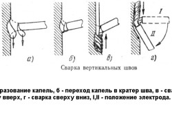
Horizontal welds. The process of welding horizontal points is associated with some difficulties. During welding with a transverse seam on a vertical surface, molten metal can flow to the lower edge. As a result, a cut may appear on the upper edge. The use of this method in welding carbon points produced in a horizontal arrangement is quite simple and does not cause any difficulties. The work itself is similar to welding in the lower position and depends on the required seam.
In general, there are six groups of failures from plastic welding. The following diagrams will help you recognize these failures. Please note that the lists below are not an assessment or ranking of failures and are not limited to a specific type of welding process or plastic material.
Of course, different applications may have special requirements, and it is impossible to cover them here. Example No. 1 - Changing sections of a pipeline. Is the pipeline used and do you need to exchange the damaged part or change the direction of the pipeline? To achieve good welding performance, consider the following. Know the material, the medium, and how much it flows through the pipe. Used pipes are dirty and need to be cleaned before you can weld them. The longer the section was used, the more difficult it would be to produce a proper weld.
Vertical welds. In the welding of vertically standing parts, the metal located below is designed to hold the melting metal from above, but at the same time it turns out to be rough and in the form of scales. It is much more difficult to get a high-quality connection when working downward. Welding of vertical seams in a standing plane is possible only in an orientation from bottom to top and vice versa.
After the cleaning process, the weld area must be dried. Moisture inside the weld can lead to some of the failures that were mentioned above. If you cannot stop the fluid from dripping, you can use the bladder. This air-like tool can be inserted and detonated inside the part. After welding is complete, you simply release the air and remove the bladder. Some environments require specific flow behavior. This can lead to the selection of a different type of welding equipment or to work on the inside of the pipe to ensure a positive flow.
Ceiling seams. The most difficult type of welding work. In the process, it is difficult to release gases and slag, and it is also difficult to keep the melt from draining and to achieve the strength of the point. But despite the observance of all ceiling welding techniques, the seams are still inferior in terms of reliability to the welds made in other positions.
Remember that it is difficult to remove the weld inside the pipe. Example No. 2 - Material with fillers. The quantity and quality of filler material inside your plastic parent material and weld rod can affect the quality of your weld. Sometimes wire materials, such as wood chips or denim, are used to provide bulk and make plastic cheaper. Consider what happens inside the weld. The molecules of the welding rod and the base material want to connect with each other, however, when the plastic molecule meets the filler molecule, they cannot mix.
Classification of features of welded joints according to the outline:
- welding of longitudinal seams;
- creation of annular seams.
To perform the longitudinal type of welding, thorough metal preparation is required at the point of the proposed welding. Part surfaces must be free of burrs, edges and bumps. In longitudinal welding, the seam is possible only with full cleaning and degreasing of the required surfaces.
Standards and Guests
An ideal connection is not possible in this case. For this application, there is a special welding wire for polyethylene with fillers. Please contact me for more information about this special rod. To ensure that the quality of the welding task meets the specifications that you and your customers require, there is testing of equipment offered by a number of suppliers for various testing applications. Another option is to send weld samples to the laboratory.
Ring welds. Circumferential welding requires great accuracy and accuracy, and calibration of welding currents is necessary immediately, especially when working with small diameters.
Welding of circular seams varies in shape. They are:
- convex;
- concave;
- flat.
Back to the table of contents
Weld Geometry
The main geometric parameters are: width, curvature, convexity and the root of the joint.
Weld Characterization
To get a representative test result, you must take a sample from the same batch of material you are working with. You must use the same parameters, the same materials, and carry them out by the same worker who produces the actual weld.
Article Search Select one or more topics to refine your search. Most welds we need to make fall into five general categories. Each of these separate categories of joints has many variations on the base unit. Understanding these five and being able to fill welds in all positions is a good starting point for anyone who learns to weld. The five main welds include butt, lap, tee, corner joint and edge joint.
Width is the gap between the visibly different faces of the fusion of metals. Curvature is the gap between the area flowing along the visible edges of the weld point and a specific metal at the point of limiting concavity.
To measure the convexity, a gap is determined relative to the levels that flows along the visible faces of the weld and base metal at the point of limiting convexity. The root is the edge that is extremely remote from the profile level, which is actually its reverse side.
The junction occurs when two elements are located side by side or connected together. Welding is carried out along the seam, which is adjacent to two adjacent parts. Depending on the thickness of the materials, the edge of the butt joint may be square, beveled or have some other kind of preparation made before its installation and welding. A butt joint can be welded on one side or on both sides depending on the requirements in the drawing or welding symbol. A joint is considered a weld.
An overlap joint is formed when two parts are stacked on top of each other at a predetermined distance along their edge. In most cases, we do not see edge preparation at the weld. The fillet of the weld is placed in the seam between two overlapping elements. As with the butt joint, the weld can be made on one side or on both sides, depending on the requirements in the drawing or welding symbol. The knee joint may contain one or more welding passes.
You can divide such seams according to dimensional norms:
- cathetus;
- thickness;
- estimated height.
In a fillet weld for fillet welding, the length from the level of the first weldment to the edge of the weld on the next part is a coal weld leg. A leg is an important characteristic that must be observed during welding. With simple coal joints with a single size, the weld leg is defined by the size of its edges. In welding T-joints, the leg has a fixed value, and a single dimension of materials is used. And when T-structures of different dimensions are used in welding operations, it is equal to the thickness of a thinner metal. The leg must be of the correct size to achieve maximum joint strength, if too large leg is used, weld defects are possible.
The connecting bolt is considered a glued welded joint. A tee joint is formed when two elements intersect at an angle of 90 °, and the edges join in the middle of the plate or component. When a pipe or tube is connected to a base plate, a tee will form. Everything around the pipe weld to the base plate is considered a tee joint. The fillet is placed between two elements depending on the size and requirements of the drawing. As with other joints, welds can be made on one side or on both sides.
Beginners can simplify work with parts by arranging them for welding “in a boat”. When welding in a boat, the likelihood of undercutting is reduced, and the lock will be stronger.
The thickness of the coal seam is the maximum distance from its level to the contact of the maximum penetration of the base metal.
What to remember when welding corner joints? For fillet welds, a concave level shape with a smooth transition to the base is considered favorable. This is due to the problematic penetration in the coal seams of the root over the entire thickness. In most cases, the leg and thickness are measured with specific patterns.
Sometimes this requires more than one to create a compressed weld. Just like knee engagement, a tee joint is also considered a fillet type weld. The corner joint is similar to a triple joint, but instead of the elements touching in the middle of the plate or component, the corner joint has two parts that intersect at an angle of 90 ° to the edge of the joint or material. Weld fillets are usually made in an area where two plates or elements intersect. There are several variations on the corner joint, one of which is called the open angle, where the corner weld is made on the outer edge.
To get the most durable connection, you need to refer to many factors. They are taken into account when determining the type of connection, depending on the required characteristics of the welded products.
Welds and joints
The other is called the closed angle, where outside welding is much more like a weld. Most people believe that the corner joint will look like fillets. As with all other welds, the weld can be made on the proximal side or on the other side.
And finally, the fifth of the five major joints is what we call the marginal joint. Two elements have their surfaces parallel to each other, creating a seam or region of the edge where welding can occur. A weld is considered a weld. We often see that an edge seam applied to sheet metal parts was edge-sealed or formed in such a way that a weld seam needs to be joined in order to join adjacent parts. Just with all the other welds, it can be done on the side on the other side or around the entire perimeter, depending on the conditions of use and maintenance.
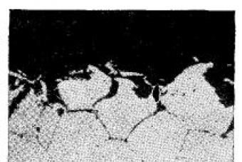
The one-piece connection that was made by welding is called welded. It consists of several zones (Fig. 77):
Weld;
Fusion;
Fig. 77. The zones of the weld: 1 - weld; 2 - fusion; 3 - thermal effects; 4 - base metal
Thermal influence;
Base metal.
The length of welded joints are:
Short (250-300 mm);
Medium (300-1000 mm);
Long (more than 1000 mm). Depending on the length of the weld, the method of its execution is also chosen. With short joints, the seam is led in one direction from the beginning to the end; middle sections are characterized by seam segregation in separate sections, and its length should be such that an integer number of electrodes (two, three) is enough to complete it; long joints are welded in the reverse step, as described above.
By type, welded joints (Fig. 78) are divided into:
1. Butt. These are the most common compounds in various welding methods. They are preferred because they are characterized by the lowest intrinsic stresses and strains. As a rule, sheet metal structures are welded with butt joints.
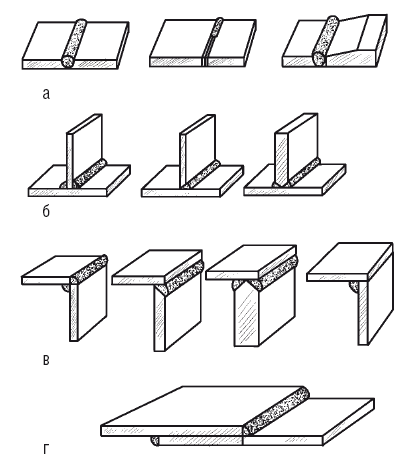
Fig. 78. Types of welded joints: a - butt; b - Tauri; in - angular; g - lap
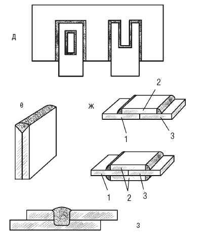
Fig. 78 (ending). d - slotted; e - end; g - with overlays; 1-3 - base metal; 2 - pad: 3 - electric rivets; h - with electric rivets
The main advantages of this compound, which can be counted on if the edges are carefully prepared and adjusted (due to the blunting of the latter, burn-through and metal flow during welding are prevented, and observing their parallelism ensures a qualitative uniform seam), are the following:
Minimum consumption of base and deposited metal;
The shortest time interval required for welding;
The connection made may not be inferior in strength to the base metal.
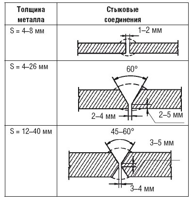
Depending on the thickness of the metal, the edges during arc welding can be cut at different angles to the surface:
At a right angle, if you connect steel sheets with a thickness of 4-8 mm. At the same time, a gap of 1–2 mm is left between them, which facilitates the boiling of the lower parts of the edges;
At a right angle, if they connect metal with a thickness of up to 3 and up to 8 mm for one- or two-sided welding, respectively;
With one-sided bevelled edges (V-different), if the metal thickness is from 4 to 26 mm;
With a two-sided bevel (X-shaped), if the sheets have a thickness of 12–40 mm, and this method is more economical than the previous one, since the amount of deposited metal is reduced by almost 2 times. This means saving electrodes and electricity. In addition, deformation and welding stresses are less characteristic of bilateral bevels;
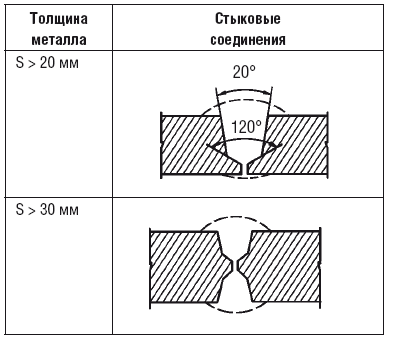
The bevel angle can be reduced from 60 ° to 45 ° by welding sheets with a thickness of more than 20 mm, which will reduce the volume of deposited metal and save electrodes. The presence of a gap of 4 mm between the edges will provide the necessary penetration of the metal.
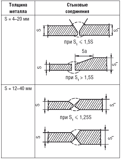
When welding metal of different thicknesses, the edge of a thicker material is mowed more strongly. With a considerable thickness of the parts or sheets connected by arc welding, a cup-shaped preparation of the edges is used, moreover, with a thickness of 20-50 mm, one-sided preparation is carried out, and with a thickness of more than 50 mm, two-sided preparation is performed.
The above is clearly shown in table. 44.
2. Lapping, most often used in arc welding of structures whose metal thickness is 10-12 mm. From the previous connection, this option is distinguished by the absence of the need to specially prepare the edges - just cut them off. Although the assembly and preparation of metal for lap joint is not so burdensome, it should be noted that the flow rate of the base and deposited metal increases compared to butt joints. To ensure reliability and avoid corrosion due to moisture between the sheets, such joints are boiled on both sides. There are types of welding where only this option is used, in particular with spot contact and roller.
3. Tauri, widespread in arc welding. For them, the edges are beveled on one or both sides, or even without a bevel. Special requirements apply only to the preparation of a vertical sheet, which should have an equally trimmed edge. With one- and two-sided bevels, the edges of the vertical sheet provide a gap of 2-3 mm between the vertical and horizontal planes to boil the vertical sheet over the entire thickness. One-sided beveling is performed in the case when the design of the product is such that it is impossible to boil it on both sides.
Table 44
The choice of butt joints depending on the thickness of the metal
5. Grooved, which resorted to in those cases when the lap seam of normal length does not provide the necessary strength. Such compounds are of two types - open and closed. The slot is made using oxygen cutting.
6. End (side), in which the sheets are laid one on top of the other and welded at the ends.
7. With overlays. To perform such a connection, the sheets are docked and overlap the joint with a cover plate, which, of course, entails an additional consumption of metal. Therefore, this method is used in the case when it is not possible to make a butt or lap seam.
8. With electric rivets. This connection is strong, but not tight enough. For him, the upper sheet is drilled and the resulting hole is welded in such a way as to capture the lower sheet.
If the metal is not too thick, then drilling is not required. For example, in automatic submerged arc welding, the top sheet is simply fused with a welding arc.
The structural element of the welded joint, which when formed is formed due to crystallization of molten metal along the line of movement of the heating source, is called a weld. Elements of its geometric shape (Fig. 79) are:
Width (b);
Height (h);
Leg size (K) for corner, lap and T-joints.
The classification of welds is based on various features, which are presented below.
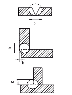
Fig. 79. Elements of the geometric shape of the weld (width, height, size of the leg)
1. By type of connection:
Butt;
Corner (Fig. 80).
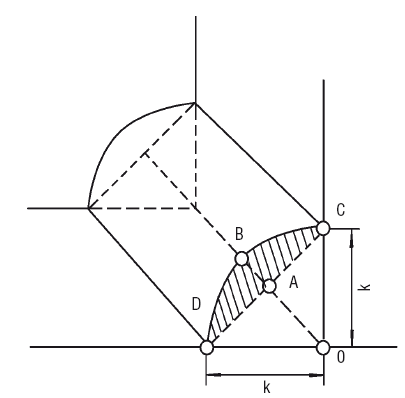
Fig. 80. The corner seam
Corner seams are practiced with some types of welded joints, in particular with lap, butt, corner and with overlays.
The sides of such a seam are called legs (k), the ABCD zone in Fig. 80 shows the degree of convexity of the seam and is not taken into account when calculating the strength of the welded joint. When performing it, it is necessary that the legs are equal, and the angle between the sides OD and BD is 45 °.
2. By type of welding:
Arc welding seams;
Seams of automatic and semi-automatic submerged arc welding;
Seams of arc welding in a protective gas environment;
Electroslag welding seams;
Resistance welding seams;
Seams of gas welding.
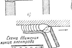
3. According to the spatial position (Fig. 81), in which welding is performed:
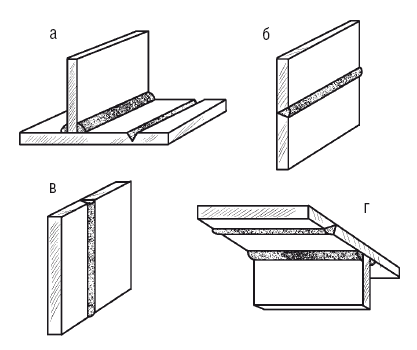
Fig. 81. Welds, depending on their spatial position: a - lower; b - horizontal; in - vertical; g - ceiling
Horizontal
Vertical
Ceiling.
The bottom seam is the easiest to do, the ceiling is the hardest.
In the latter case, welders undergo special training, and the ceiling seam is easier to do with gas welding than arc welding.
4. By length:
Continuous
Intermittent (Fig. 82).
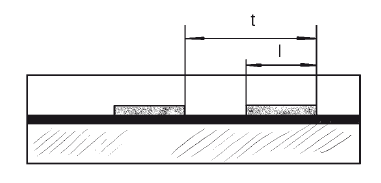
Fig. 82. Intermittent weld
Intermittent seams are practiced quite widely, especially in cases where there is no need (strength analysis does not imply a continuous seam) to tightly connect the products.
The length (l) of the joined sections is 50–150 mm, the gap between them is approximately 1.5–2.5 times greater than the weld zone, and together they form a weld pitch (t).
5. According to the degree of convexity, ie, the shape of the outer surface (Fig. 83):
Normal;
Convex;
Concave.
The type of electrode used determines the seam bulge (a ‘). The greatest convexity is characteristic of thin-coated electrodes, and thick-coated electrodes give normal seams, since they are characterized by a greater fluidity of the molten metal.
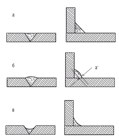
Fig. 83. Welds, differing in the shape of the outer surface: a - normal; b - convex in - concave
It was experimentally established that the strength of the seam does not increase with an increase in its convexity, especially if the joint "works" under variable loads and vibration. This situation is explained as follows: when making a weld with a large convexity, it is impossible to achieve a smooth transition from the weld bead to the base metal, therefore, at this point, the edge of the weld seems to be cut, and stresses are mainly concentrated here.
Under conditions of variable and vibrational loads in this place, the weld may be destroyed. In addition, convex seams require increased consumption of electrode metal, energy and time, i.e., it is an uneconomical option.
6. By configuration (Fig. 84):
Straightforward;
Ring;
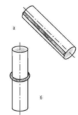
Fig. 84. Welds of various configurations: a - rectilinear; b - ring
Vertical
Horizontal
7. In relation to the acting forces (Fig. 85):
Flank;
Face;
Combined
Slanting. The action vector of external forces can be parallel to the axis of the seam (typical for flanking), perpendicular to the axis of the seam (for frontal), pass at an angle to the axis (for oblique), or combine the direction of the flanking and frontal forces (when combined).
8. According to the method of holding molten weld metal:
Without linings and pillows;
On removable and remaining steel linings;
![]()
Fig. 85. Welds in relation to the acting forces: a - flank; b - butt; in - combined; g - oblique
On copper, flux-copper, ceramic and asbestos linings, flux and gas pads.
When applying the first layer of the seam, the main thing is to be able to hold liquid metal in the weld pool.
To prevent its leakage, use:
Steel, copper, asbestos and ceramic linings, which are brought under the root seam. Thanks to them, it is possible to increase the welding current, which ensures through penetration of the edges and guarantees a complete penetration of parts. In addition, the pads hold molten metal in the weld pool, preventing the formation of burns;
Inserts between the welded edges, which perform the same functions as the gaskets;
Cutting and welding of the root of the seam from the opposite side, while not striving for through penetration;
Flux, flux-copper (for submerged arc welding) and gas (for manual arc, automatic and argon-arc welding) cushions that bring or deliver under the first layer of the seam. Their goal is to prevent metal from flowing out of the weld pool;
Connections to the lock when making butt seams that prevent burns in the root layer of the seam;
Special electrodes, the coating of which contains special components that increase the surface tension of the metal and prevent it from flowing out of the weld pool when performing vertical seams from top to bottom;
The pulse arc, due to which short-term melting of the metal occurs, which contributes to faster cooling and crystallization of the weld metal.
9. On the side on which the seam is laid (Fig. 86):
One-way;
Bilateral.
10. For materials to be welded:
On carbon and alloy steels;
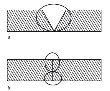
Fig. 86. Welds, differing in their location: a - one-sided; b - bilateral
On non-ferrous metals;
On bimetal;
On foam and polyethylene.
11. The location of the connected parts:
At an acute or obtuse angle;
At right angles;
In one plane.
12. By volume of deposited metal (Fig. 87):
Normal;
Weakened;
Reinforced.
13. By location on the product:
Longitudinal;
Transverse.
14. In the form of welded structures:
On flat surfaces;
On spherical surfaces.
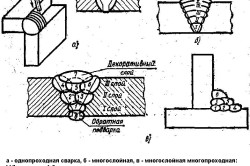
15. By the number of deposited rollers (Fig. 88):
Single layer;
Multilayer;
Multipass
Before welding, the edges of the connected products, structures or parts must be properly prepared, since the strength of the seam depends on their geometric shape
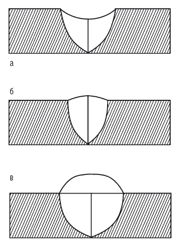
Fig. 87. Welds, differing in the volume of deposited metal: a - weakened; b - normal; in - reinforced
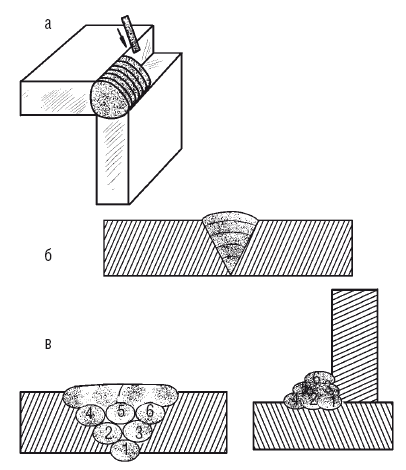
Fig. 88. Welds, differing in the number of deposited rollers: a - single layer; b - multilayer; c - multilayer multipass
The elements of the preparation of the form are (Fig. 89):
The angle of cutting the edge (?), Which must be performed if the thickness of the metal is more than 3 mm. If you skip this operation, then negative consequences are possible, such as lack of penetration of the welded joint cross section, overheating and burnout of the metal. Cutting the edges makes it possible to carry out welding with several layers of a small cross section, due to which the structure of the welded joint is improved, and internal stresses and strains are reduced;
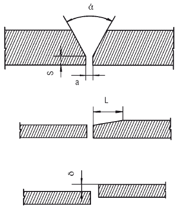
Fig. 89. Elements for the preparation of chrome
The gap between the joined edges (a). From the correctness of the set gap and the selected welding mode, it depends on how complete the penetration in the joint section will be during the formation of the first (root) layer of the seam;
The blunting of the edges (S) is necessary in order to give the root suturing process a certain stability. Ignoring this requirement leads to burnout of the metal during welding;
The length of the bevel of the sheet in case there is a difference in thickness (L). This element allows for a smooth and gradual transition from a thicker part to a thin one, which reduces or eliminates the risk of stress concentration in welded structures;
The offset of the edges relative to each other (?). Since this reduces the strength characteristics of the joint, and also contributes to the lack of penetration of the metal and the formation of foci of stress, GOST 5264–80 sets acceptable standards, in particular, the displacement should be no more than 10% of the metal thickness (maximum 3 mm).
Thus, in preparation for welding, the following requirements must be met:
To clear edges from pollution and corrosion;
Chamfer the appropriate size (according to GOST);
Set the gap in accordance with GOST developed for a particular type of connection.
Some types of edges were already mentioned earlier (although they were considered in another aspect) in the description of butt joints, but nevertheless it is necessary to focus attention on this again (Fig. 90).
The choice of a particular type of edge is determined by a number of factors:
By welding method;
Thick metal;
By the method of connecting products, parts, etc.
A separate standard has been developed for each welding method, which indicates the form of preparation of the edges, the size of the seam and the permissible deviations. For example, manual arc welding is carried out in accordance with GOST 5264–80, contact welding in accordance with GOST 15878–79, electroslag welding in accordance with GOST 15164–68, etc.
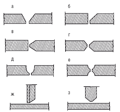
Fig. 90. Types of edges prepared for welding: a - with a bevel on both edges; b - with a bevel of one edge; in - with two symmetrical bevels of one edge; g - with two symmetrical bevels of two edges; d - with a curved bevel of two edges; e - with two symmetrical curved bevels of two edges; g - with a bevel of one edge; h - with two symmetrical bevels of one edge
In addition, there is a standard for the graphic designation of the weld, in particular GOST 2.312–72. To do this, use an oblique line with a one-sided arrow (Fig. 91), which indicates the section of the seam.
The weld characteristics, the recommended welding method and other information are presented above or below the horizontal shelf connected to the inclined arrow line. If the seam is visible, i.e., located on the front side, then the seam characteristic is given above the shelf, if invisible, under it.
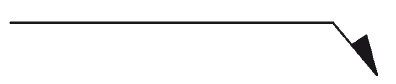
Fig. 91. Graphic designation of welds
The symbols for the weld also include additional signs (Fig. 92).
For various types of welding, the letter designations are accepted:
Arc welding - E, but since this type is the most common, the letter may not be indicated in the drawings;
Gas welding - G;
Electroslag welding - Ш;
Inert gas welding - And;
Explosion welding - Vz;
Plasma welding - Pl;
Resistance welding - CT;
Friction welding - Tr;
Cold welding - X.
If necessary (if several welding methods are implemented), the letter designation of the welding method used is placed before the designation of a particular variety:
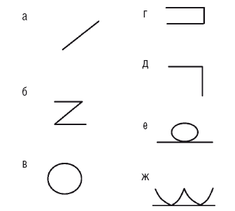
Fig. 92. Additional designations of the weld: a - intermittent seam with a chain sequence of sections; b - intermittent seam with a staggered sequence of sections; in - a seam in a closed loop; g - seam along an open circuit; d - mounting seam; e - seam with removed reinforcement; g - seam with a smooth transition to the base metal
Manual - P;
Semi-automatic - P;
Automatic - A.
Submerged arc - F;
Welding in active gas with a consumable electrode - UP;
Inert gas welding with a consumable electrode - IP;
Inert gas welding with a nonconsumable electrode - IN.
For welded joints there are also special lettering:
Butt - С;
Tauris - T;
Lap - N;
Angular - U. By the numbers affixed after the letters, determine the number of the welded joint in accordance with GOST for welding.
Summarizing the above, it can be stated that the symbols of the weld are added to a certain structure (Fig. 93).
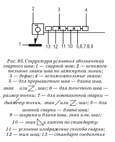
Fig. 93. The structure of the symbols of the weld: 1 - weld; 2 - auxiliary signs of a seam in a closed line; 3 - hyphen; 4 - auxiliary signs; 5 - for intermittent seam - seam length, sign or, step; 6 - for a point seam - the size of the point; 7 - for resistance welding - diameter of a point, sign or, step; 8– for seam welding - seam length; 9 - width and length of the seam, sign or, step; 10 - sign and leg according to the standard; 11 is a conditional image of a welding method; 12 - type of seam; 13 - connection standard
As an example, we decipher the notation:
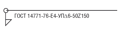
The seam is located on the invisible side - the designation is under the shelf;
T-joint, seam No. 4 according to GOST 14771–76 - T4;
Welding in carbon dioxide - U;
Semi-automatic welding - P;