Literature: [L.1], p. 40
As an example, we present the expansion in the Fourier series periodic sequence rectangular pulses with amplitude , duration and repetition period , symmetrical about zero, i.e.
 , (2.10)
Here 
The expansion of such a signal in a Fourier series gives
 , (2.11)
where is the duty cycle.
To simplify the notation, we can introduce the notation
 , (2.12)
Then (2.11) is written as follows
 , (2.13)
On fig. 2.3 shows a sequence of rectangular pulses. The spectrum of the sequence, as well as any other periodic signal, is discrete (linear) in nature.
The envelope of the spectrum (Fig. 2.3, b) is proportional to  . The distance along the frequency axis between two neighboring components of the spectrum is , and between two zero values (width of the spectrum lobe) is . The number of harmonic components within one lobe, including the zero value on the right in the figure, is , where the sign means rounding to the nearest integer less (if the duty cycle is a fractional number), or (with an integer value of the duty cycle). As the period increases, the fundamental frequency
  decreases, the spectral components in the diagram converge, the amplitudes of the harmonics also decrease. In this case, the shape of the envelope is preserved.


When solving practical problems of spectral analysis, cyclic frequencies are used instead of angular frequencies  measured in Hertz. Obviously, the distance between neighboring harmonics in the diagram will be , and the width of one lobe of the spectrum will be . These values are shown in parentheses in the diagram.
In practical radio engineering, in most cases, instead of the spectral representation (Fig. 2.3, b), spectral diagrams of the amplitude and phase spectra are used. The amplitude spectrum of a sequence of rectangular pulses is shown in fig. 2.3, c.
Obviously, the envelope amplitude spectrum proportional  .
.
As for the phase spectrum (Fig. 2.3, d), it is believed that the initial phases of the harmonic components change abruptly by the value -π when changing the sign of the envelope sinc kπ/q. The initial phases of the harmonics of the first lobe are assumed to be zero. Then the initial phases of the harmonics of the second lobe will be φ = -π , third petal φ = -2π etc.
Consider another representation of the signal by a Fourier series. To do this, we use the Euler formula
 .
.
In accordance with this k-th formula component (2.9) of the expansion of the signal into a Fourier series can be represented as follows
 ;
;  . (2.15)
Here, the quantities and are complex and represent the complex amplitudes of the spectrum components. Then the series
Fourier (2.8), taking into account (2.14), takes the following form
 , (2.16)
 , (2.17)
It is easy to verify that the expansion (2.16) is carried out in terms of the basis functions  , which are also orthogonal on the interval
  , i.e.

Expression (2.16) is complex form Fourier series that extends to negative frequencies. Quantities and  , where denotes the complex conjugate of a quantity, are called complex amplitudes spectrum. Because is a complex quantity, it follows from (2.15) that
 And
And  .
.
Then the set is the amplitude, and the set is the phase spectrum of the signal.

On fig. 2.4 shows the spectral diagram of the spectrum of the above sequence of rectangular pulses, represented by the complex Fourier series

The spectrum also has a line character, but unlike the previously considered spectra, it is determined both in the region of positive and in the region of negative frequencies. Since is an even function of the argument , the spectral diagram is symmetric about zero.
Based on (2.15), we can establish a correspondence between and coefficients and expansions (2.3). Because
 And
And  ,
,
then as a result we get
 . (2.18)
Expressions (2.5) and (2.18) allow us to find the values in practical calculations.
Let us give a geometric interpretation of the complex form of the Fourier series. Let's single out the k-th component of the signal spectrum. In an integrated k-th form component is described by the formula
where and are determined by expressions (2.15).
In the complex plane, each of the terms in (2.19) is represented as vectors of length  , rotated through an angle and relative to the real axis and rotating in opposite directions with frequency (Fig. 2.5).
Obviously, the sum of these vectors gives a vector located on the real axis, the length of which is . But this vector corresponds to the harmonic component


As for the projections of vectors on the imaginary axis, these projections have equal length, but opposite directions and add up to zero. This means that the signals presented in the complex form (2.16) are in fact real signals. In other words, the complex form of the Fourier series is mathematical abstraction, which is very convenient for solving a number of problems of spectral analysis. Therefore, sometimes the spectrum defined by the trigonometric Fourier series is called physical spectrum, and the complex form of the Fourier series is mathematical spectrum.
In conclusion, let us consider the issue of energy and power distribution in the spectrum of a periodic signal. To do this, we use Parseval's equality (1.42). When the signal is expanded into a trigonometric Fourier series, expression (1.42) takes the form
 .
.
DC energy
 ,
,
and the energy of the kth harmonic
 .
.
Then the signal energy
 . (2.20)
Because average signal strength
 ,
,
then, taking into account (2.18),
 . (2.21)
When the signal is decomposed into complex series The Fourier expression (1.42) has the form
 ,
,
where  is the energy of the k-th harmonic.
The signal energy in this case
 ,
,
and its average power
 .
.
It follows from the above expressions that the energy or average power of the k-th spectral component of the mathematical spectrum is half the energy or power of the corresponding spectral component of the physical spectrum. This is due to the fact that the physical spectrum is distributed equally between and the mathematical spectrum.
| -τ and /2 |
| τ and /2 |
| T |
| t |
| U 0 |
| S(t) |
Task No. 1, group RI - 210701
In electronic equipment for various applications, periodic sequences of rectangular pulses are widely used. In this case, the ratios of the pulse duration τ and the oscillation period T may differ greatly. For example, vibrations that generate clock generators, which determine the "tempo" of computers, are characterized by comparable values of τ and T, and the pulses used in radar can be hundreds of times shorter than the period. Attitude T/τ is called pulse duty cycle, and the reciprocal (τ/ T) - fill factor.
Rice. 6. The sequence of rectangular pulses (a) and the coefficients of the Fourier series (b)
Consider a sequence of rectangular pulses with amplitude BUT, duration τ and following with a period T(Fig. 6, but). We choose the origin of the time as shown in the figure, that is, so that the pulse is symmetrical about the zero mark, and calculate the coefficients of the Fourier series (1). Since the function s(t) with this position of the axes turns out to be even, all b n are equal to zero, and for a n we get:
The Fourier series for a sequence of rectangular pulses takes the form:
 (6)
(6)
The values of the coefficients of the Fourier series, calculated by formulas (5), are shown in the spectral diagram shown in fig. 6, b.
Odds a n can be associated with a function  . Indeed, they will be proportional (with a factor
  ) function values
  with arguments corresponding to harmonic frequencies. This can be seen if expression (5) is rewritten as follows:
 (7)
(7)
So a function like  is an envelope for coefficients Fourier expansions a sequence of rectangular pulses (see Fig. 6, b). The position of the zeros of the envelope on the frequency axis f can be found from the condition
  or
or  , where. The first time the envelope vanishes at a frequency f= 1/τ (or ω = 2π/τ). Further, the zeros of the envelope are repeated at f\u003d 2 / τ, 3 / τ, etc. These frequencies can coincide (for integer duty cycles) with the frequencies of any harmonics of the spectrum, and these frequency components will disappear from the Fourier series. If the duty cycle is an integer, the period T exactly a multiple of the pulse duration. Then, between the two zeros of the envelope, the harmonics of the spectrum will be located in the amount q-
1.
Table 1 illustrates how the pulse parameters are related in time and frequency representations. 2. With increasing period T the harmonics on the spectral diagram are approaching (the spectrum becomes "thicker"). However, changing only the period does not lead to a change in the shape of the envelope of the amplitude spectrum. The evolution of the envelope (shift of its zeros) depends on the pulse duration. Shown here is the evolution of amplitude spectral diagrams for sequences of rectangular pulses that vary in pulse durations and periods. The ordinates of the spectral diagrams show the relative values of the harmonic amplitudes:  They are calculated according to the formulas:
 (8)
(8)
Table 2. Oscillograms and spectrograms of rectangular pulse sequences

2.5. Spectra of chaotic (noise) oscillations
Chaotic oscillation s(t) - this random process. Each of its implementation under unchanged conditions is not repeated, it is unique. In electronics, chaotic oscillations are associated with noises- fluctuations of currents and voltages, changing randomly due to the random movement of charge carriers. In this context, chaotic and noise oscillations are considered synonymous.
Rice. 7. Structural diagram of the measurement of the mean square noise voltage
Noise fluctuation can be described in the frequency representation: it is associated with a certain spectral characteristic, and for a random process it is continuous. The theoretical foundations of the spectral decomposition of chaotic oscillations are set out in. Without plunging into a rigorous theory, we will explain the methodology for the experimental study of statistical parameters noise voltage s(t) according to the scheme shown in Fig. 8.
R  is. 8. Scheme for measuring the spectral density of noise voltage intensity
Let's skip the noise voltage s(t) through a filter that releases the energy of oscillations in a narrow band  near frequency f. Subject to the condition
  <<
f the oscillation at the output of the filter will resemble a sinusoid with a frequency f. However, the amplitude and phase of this sinusoid are subject to chaotic changes. With filter bandwidth reduction
  the shape of the output oscillation is getting closer and closer to a sinusoid. Its amplitude decreases, but the ratio of the mean square of the voltage passing through the filter (
  ), to the bandwidth
  remains finite and tends to a certain limit with a successive decrease in the band W(f):
limit value W(f) are called intensity spectral density process s(t).
It is equal to the average intensity of the harmonic components per unit interval of the frequency axis. When measuring W(f) use a narrow-band tunable filter that can be tuned to any frequency within a given measurement range. The noise voltage passing through the filter is subjected to quadratic detection and averaged (integrated). The result is the mean square:  . Further along the known filter band
  calculate W(f).
The full intensity of the process- middle square
  - is found by integrating the spectral components of the noise over all frequencies:
 (10)
(10)
To prepare for work, you should study this manual in full. More detailed information on the topic of laboratory work can be found in the chapter "Frequency spectra of electrical oscillations, spectral analysis" of the book.
2. Spectrum of a periodic sequence of rectangular pulses
Consider a periodic sequence of rectangular pulses shown in fig. 5. This signal is characterized by the pulse duration, its amplitude and period. The voltage is plotted along the vertical axis.
Fig.5. Periodic sequence of rectangular pulses
Let's choose the beginning of counting in the middle of the pulse. Then the signal is decomposed only in cosines. Harmonic frequencies are n/T , where n- any integer. The amplitudes of the harmonics according to (1.2.) will be equal to:

because V(t)=E at , where is the pulse duration and V(t)=0 at , then

This formula can be conveniently written as:
 (2.1.)

Fig.6. Periodic Sequence Spectrum
square pulses.
When constructing the envelope, we mean that - is
An oscillating function of frequency, and the denominator increases monotonically with increasing frequency. Therefore, a quasi-oscillating function with a gradual decrease is obtained. When the frequency tends to zero, both the numerator and the denominator tend to zero at the same time, their ratio tends to unity (the first classical limit). Zero values of the envelope occur at points where i.e.
Where mis an integer (exceptm
Classification of signals and their parameters.
Electrical signals are electrical processes used to transmit or store information.
Signals can be divided into two large classes: deterministic and random. Signals are called deterministic if their instantaneous values at any moment of time can be predicted with a probability equal to one and which are given as a certain definite function of time. Here are some typical examples: a harmonic signal with a known amplitude A and period T(Fig. 1.1 but); a sequence of rectangular pulses with a known repetition period T, duration t and and amplitude A(Fig. 1.1 b); a sequence of pulses of arbitrary shape with known duration t and amplitude A and period T(Fig. 1.1 in). Deterministic signals do not contain any information.
Random signals are chaotic functions of time, the values of which are not known in advance and cannot be predicted with a probability equal to one (a single pulse with duration t and amplitude A(Fig. 1.1 G) speech, music in terms of electrical quantities). Random signals also include noise.
The deterministic signals, in turn, are subdivided into periodic ones, for which the condition S(t)=S(t+kT), where T- period k-any integer, and S(t) is understood as a time-varying current, voltage or charge (Fig. 1.1 a B C).
Obviously, any deterministic signal for which the condition S(t)¹ S(t+kT).
The simplest periodic signal is a harmonic signal of the form  .
.
Any complex periodic signal can be decomposed into harmonic components. Below, such a decomposition will be carried out for several specific types of signals.
A high-frequency harmonic signal, in which information is embedded by modulation, is called a radio signal (Fig. 1.1 d).
periodic signals.
 Any complex periodic signal S(t)=S(t+kT) (Fig. 1.2), given on the interval of values t from –¥ to +¥, can be represented as a sum of elementary harmonic signals. This representation is carried out in the form of a Fourier series, if only the given periodic function satisfies the Dirichlet conditions:
1. On any finite time interval, the function S(t) must be continuous or have a finite number of discontinuities of the first kind.
2. Within one period, the function must have a finite number of highs and lows.
Usually all real radio signals satisfy these conditions. In trigonometric form, the Fourier series has the form (1.1)
where the constant component is  (1.2)
(1.2)
and the coefficients a n , And b n for cosine and sinusoidal terms, the expansions are determined by the expressions  (1.3)
(1.3)
Amplitude (modulo) and phase (argument) n-th harmonics are expressed in terms of coefficients a n , And b n in the following way ![]() (1.4)
(1.4)
When using the complex notation, the expression for the signal S(t) takes the form ![]() . Here the coefficients
. Here the coefficients ![]() , called complex amplitudes, are
, called complex amplitudes, are  and are related to the values a n and b n by the formulas: for n>0, and for n<0. С учётом обозначений
  .
.
The spectrum of a periodic function consists of individual lines corresponding to discrete frequencies 0, w, 2w, 3w ..., i.e. it has a line or discrete character (Fig. 1.3). The use of Fourier series in combination with the principle of superposition is a powerful tool for analyzing the influence of linear systems on the passage of various types of periodic signals through them.
When expanding a periodic function into a Fourier series, one should take into account the symmetry of the function itself, since this allows us to simplify the calculations. Depending on the type of symmetry, the functions represented by the Fourier series can:
1.  Do not have a constant component if the area of the figure for the positive half-cycle is equal to the area of the figure for the negative half-cycle.
2. Do not have even harmonics and a constant component, if the function values are repeated after half a period with the opposite sign.
Spectral composition of a sequence of rectangular pulses at different periods of their duty cycle.
A periodic sequence of rectangular pulses is shown in fig. 1.4. The constant component of the Fourier series is determined from the expression  and for this case is equal to
  .
.
 Amplitude cos-component a n is equal to
 , and the amplitude of the sin-component b n is equal to
 ![]() .
.
Amplitude n th harmonic ![]()

The spectral representation of time functions is widely used in communication theory. For theoretical and experimental studies of the characteristics of electrical circuits and transmission of messages over communication channels, various types of signals are used: harmonic oscillations, levels of constant voltages, sequences of rectangular and radio pulses, etc. Computational signals in the form of a unit function play a particularly important role in theoretical studies of electrical circuits and impulse function (Dirac functions). Let us determine the spectra of the most common typical signals.
11.1 Spectrum of a train of rectangular pulses
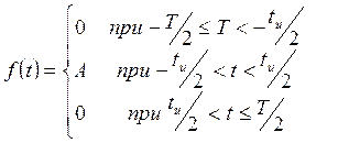
Let there be a periodic sequence of rectangular pulses with period T, pulse duration t and and amplitude A. The analytical expression for the function describing the pulse on the segment has the form
 (11.1)
The graph of the periodic sequence of pulses is shown in Figure 11.1.

Figure 11.1
This function is even, since its graph is symmetrical about the y-axis. Then the Fourier coefficients of this function are calculated by the formulas (KFT2), where .

The number represents the average value of the function over the period and is called the constant component. The frequency is called the fundamental, or first harmonic, and the frequencies k are higher harmonics, where k = 2,3,4, ...
Let us construct the amplitude spectrum of the considered sequence of rectangular pulses. Since the function is periodic, its amplitude spectrum is line-like. Denote by the distance between any neighboring harmonics. Obviously it is equal to . The amplitude of the kth harmonic according to (11.2) has the form
 (11.3)
Let us find the relationship between the period T and the pulse duration , at which the amplitude of the kth harmonic vanishes.
A 2 ≈32V, A 3 ≈15V, A 4 ≈0, A 5 ≈6.36V, A 6 ≈10.5V, A 7 ≈6.36V, A 8 ≈0, A 9 ≈4.95V, A 10 ≈6.37V.
The amplitude spectrum obtained as a result of the calculation is shown in Figure 11.2.

Figure 11.2
Such a spectrum is called a line or discrete spectrum.
The spectra for q=8 and q=16 are calculated and plotted similarly. They are shown in figures 11.3 and 11.4 respectively.
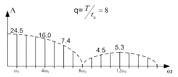
Figure 11.3

Figure 11.4
It can be seen from the figure that the greater the duty cycle of the rectangular pulses, the less important is the amplitude of the first harmonic, but the slower the spectrum decreases.
11.2 Spectrum of a single rectangular pulse
Consider Ф (11.1) for the case when Т→∞, that is, a periodic sequence of pulses degenerates into a single rectangular pulse, duration t u .
The analytical expression for this momentum is written as:
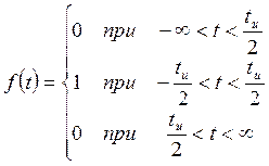
The graph of this function is shown in Figure 11.5.
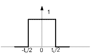
Figure 11.5
In this case, the frequency of the first harmonic and the distance between harmonics becomes equal to 0, therefore, the spectrum turns from discrete into continuous, consisting of an infinite number of spectral lines located at infinitesimal distances from each other. Such a spectrum is called continuous. This implies the most important rule: periodic signals generate discrete spectra, and non-periodic signals - continuous (continuous).
The spectrum of a rectangular single pulse can be found directly from the direct Fourier transform (10.1)
