Automatic water supply of a private house
A complete list of information on how to make and set up an automatic water supply system in a private house.
This article is a complete tutorial, for dummies! Even experienced professionals can learn something!
In this article, you will learn how to make automatic water supply in a private house with their own hands. This article is a complete tutorial for dummies. You yourself, according to these recommendations, will be able to properly assemble and mount the entire automatic water supply system, from the borehole pump to the outlets to the points of water consumption.
This course was developed by a specialist with many years of experience in the water and water industry. According to my recommendations, you yourself will be able to install the water supply, unless of course your hands grow from where it is necessary! :-)
You are sure to find answers to the most pressing questions:
| - Automatic water supply station - What should be the water supply scheme - How to equip a well (what should be the well and the level of the well from the floor). - Pumps for wells. How to well - How to connect and bring the water supply pipeline - How to assemble an automatic circuit that will: turn on and off the well pump as needed? - Filter system for a private house - Power supply to the borehole pump - Setting thresholds for switching on and off pumps - Hydraulic accumulator () for water supply. Connecting the accumulator - Heating cable for plumbing. Pipeline freezing safety - Operation and frequent system malfunctions |
Video: Well construction
How to equip a well
There are a variety of wells. Artesian wells will not be considered, they have a different system. The most common standard well today is a well with a depth of 25 to 50 meters. We will consider it.
And so you have a well ready. If not, then contact the organizations that drill wells for water.
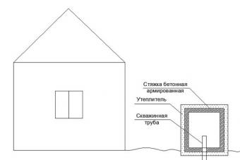
Consider the most common case when the well is located on the street near the house. You have a pipe sticking out of the ground with a diameter of 100-159 mm. If in your area the water level does not rise below two meters above ground level, then you are in luck. You can make a well for a well. I mean, it can be difficult to make wells in swampy places, since there are floods of upper water into the well itself. Well, in swampy places it is not advisable to make wells. In marshy places, you will have to make small insulated closed extensions above ground level. The extension should provide an opportunity to service the well system. And that is the ability to change the pump, and the possibility of cleaning the well itself. If we take into account the very room in which the borehole will be located, then it must be at least 1x1 meter wide and at least 1 meter high, provided that there is a hatch above the borehole pipe. If there is a side door, then up to 2 meters high. To be able to lower the pump along with the water supply. It is better to insulate this building from all sides (including the top and bottom) with a polystyrene foam plate in the form of foam plastic with a thickness of at least 100 mm. Since it makes no sense to heat this room. In order for the water in the pipe not to freeze, it is necessary to overlay the pipe with a heating cable. We will talk about the heating cable later. The borehole pipe from the floor level must be at least 400mm. just in case from accidental floods, so that the upper waters do not fall into the well. (See image)

For the place of the concrete screed, you can lay a brick or cinder block, at your discretion.
If the place is not swampy and there is an opportunity to make a well.
Let's call a well a room located below ground level. This well also needs to be insulated with a polystyrene foam plate in the form of foam plastic with a thickness of at least 100 mm. We produce insulation so that the water in the pipe does not freeze in the winter. But even with such a well insulation, it is still necessary to attach a heating cable along the pipe for insurance. The borehole should also not be lower than 400mm from the floor level. (See image)
The hatch or any other doors in winter should be solidly insulated. If the doors or the hatch are not insulated, then soft cotton wool can be laid on the entire space of the pipeline for additional insulation. A well is considered a more reliable device for a well. Since it is in the ground and because of this it will be much warmer in it and the risk of freezing the pipe is minimal. Since the temperature of +8 degrees Celsius comes out of the inner layers of the earth. The deeper the well, the warmer it will be in the well.
How to conduct plumbing from the well to the house?
Video Lesson:
Consider an image

The one in the picture is perfect. The pipe must be 2 meters below ground level. In this case, the pipe may freeze at the lifting points. Especially near the foundation, which is not insulated from the outside. By the way, the foundation must be insulated at least to a depth of 1 meter.
The pipe must be well insulated and a self-regulating heating cable must be attached to the pipe.
Secondly, a short story about how to understand this scheme. The diagram has vertical dimensions. It is necessary to mentally cut off all the turns of the pipeline - they do not exist. In addition, the calculation calculation does not affect the horizontal pipeline. All you need to know is their altitude. Since in most cases the length of horizontally located is very small and does not exceed 30 meters. 30 meters is very small and not worth counting. The difference does not exceed 10%. And also the horizontal pipeline adds only dynamic hydraulic resistance. And for the calculation, we need to know only the pressure created by the height.
Thirdly, Pressure and pressure are synonyms. Pressure of 1 bar = 10 meters of head.
To be more precise:
Downhole pump calculation program:
For calculation the first step is to know or select the appropriate pressure in the tap of the last (second) floor. For a private house, you can take from 10 to 25 meters of pressure. For example, in the central water supply, in apartments this redistribution is from 20-40 meters. 10 meters is considered an economical option and is quite suitable for water supply. In addition, the lower the pressure, the more you save the electricity consumed by the pump - a fact!
For example, remember, come in handy: I choose 10 meters of minimum pressure in the tap on the second floor.
Accordingly, the minimum pressure in the crane of the 1st floor will be equal to the difference in height. If the floor is 3 meters, then the minimum head = 13 meters.
The automatic pressure switch unit is located from the second floor crane at a height lower by 6 meters. This means that the minimum pressure in the pressure switch will be 16 meters. And so the threshold for turning on the pump will be 16 meters (1.6 bar).
We add another 15 meters to 16 meters and get the maximum relay pressure. That is, the threshold for switching off the relay should be equal to 31 meters. You can, of course, for economy and add 10 meters. And then get a shutdown threshold of 26 meters and you will also be right.
And so we choose the pump shutdown threshold of 31 meters.
To find this pressure you need to know:
Most experts will not immediately tell you the minimum column of water. The minimum water column is determined practically. If you do not have such data, then you can safely take into account the minimum height of the pump from the bottom. That is, in our case, we take for the minimum column of water where the pump is located (the top point of the pump).
Data for our case:
Payment: Set head = Well depth - minimum water column + height (from the ground to the relay automation) + Maximum pressure switch head. Total \u003d 30 - 10 + 2 + 31 \u003d 53 meters.
Having practiced a little in the calculations, you can consider it differently - easier. We need to know the height from minimum column of water up to the mark in maximum head. See diagram above.
1. To make up for losses in the event of a voltage drop in the network. When the voltage in the network drops, then the pressure of the pump itself drops.
2. To achieve a good maximum pressure threshold. If you select the pump head with the set head, a situation may arise when the pump cannot reach the maximum pressure threshold on the relay. And the system will hang in limbo. Very often in this case, the pumps burn out. If your voltage is weak, then put voltage stabilizers.
Maximum pump head will be equal to 120% of the set pressure.
In our case: Maximum pump head = set head x 1.2 = 53 x 1.2 = 63.6 meters.
This is exactly what I was looking for!!! The final will be equal to: 63.6 meters.
If you often experience voltage drops, it is better to install a voltage stabilizer on the pump.
Keep in mind that the greater the head and flow of the pump, the more electricity it consumes. The greater the flow rate and velocity of water in the pipe, the greater the pressure loss in the pipeline. Excessive losses in the pipeline can take excess energy from the pump for pumping water. Thus, the system becomes uneconomical. And these pumps consume about 1-1.5 kW.
Downhole pump chart with parameters (Head 70 meters and flow rate up to 4 m3/Hour).

The greatest demand is for pumps with a head of 60-80 meters. And flow rate up to 4 m3/hour.
If you have more than three bathrooms with baths or showers in your house, then you should pay attention to the flow rate, that 3-4 m3/h may not be enough. And if you have a swimming pool in your house, then it is better to take a pump with a flow rate of up to 10 m3 / h. Keep in mind about the resource of the well that the water in the well may run out. If the resource of the well is small and the water in the well often runs out, then you do not need a large pump flow. Practice and calculations show that a large flow rate is not economical in terms of hydraulics. For economical operation of a pump with a large flow rate, it is required to increase it so that there are no pressure losses in the pipes. Head losses take additional electricity.
For a pump with a flow rate of up to 10 m3/h, a diameter of more than 32 mm is required. For pipes with a diameter of up to 32 mm, a pump with a flow rate of up to 4 m3 / h is suitable.
Do you want to accurately calculate hydraulics and heat engineering? Or produce hydraulic calculation? Then get acquainted with my personally developed section of Hydraulics and thermal engineering
The graph shows that the higher the rise, the less water is consumed from the well. So pay attention to the water consumption, will it be sufficient for you?
About the pump:
The pump should be at a distance of 1-2 meters from the bottom.
If the water column is not small and reaches 20 meters, then the pump can not be lowered much and left 3 meters from the bottom. It is also harmful to leave it very deep at the bottom, the pump can silt up, and then you simply won’t pull it out. The main rule, if you lowered the pump, then you need to use it! If you leave it for a whole winter, then in a deep position it can be clogged with water silt, clay and other sand.
Downhole pump installation technologies.
see picture

It is better to use water supply in a well from a 32mm HDPE pipe, since it is cheaper and no special reliability is required inside the well.
American 1" Necessary in case of well repair. This collapsible connection is designed to disconnect the well pipe. In order to pull out the entire HDPE pipe along with the pump.
Borehole head designed to be worn on the well pipe in order to: Exclude debris from entering the well pipe. And also for holding and cable. The cable is designed to hold the pump at a certain depth. It is better to use a cable made of stainless steel with a thickness of at least 4 mm in diameter. Or steel insulated cable. Cable fasteners are also better from stainless steel. A nylon thread 5 mm thick is also allowed.

check valve serves to prevent backflow of water. That is, so that the pumped water does not return to the well again. Also note that there are pumps on the market with a built-in check valve.
How to lower the pump into the well?
To do this, connect to the pump, then pick up the HDPE 32 pipe. Next, hook the cable through special cable clamps. It will be more convenient to do it together. Put the lower part of the well head on the well pipe together with the sealing rubber. In the process of lowering the pump, after 1.5 meters, fix the electrical cable to the HD32 pipe with plastic clamps. Fix the electrical cable with a margin so that it does not break when stretching the pipe. Plastic clamps are sold in electrical stores.
Lower the pump to the bottom, it rests and then raise it to the required distance of 1-2 meters. Fix the position, cut off the excess pipe, push the pipe through the head, fix the cable and fix the borehole head.
And so, after the pump is lowered into the well and the pipe is brought into the house, the next step is to assemble the automatic water supply system.
The most ideal and common scheme is:
Private house water supply scheme

More on the video!
Flask with cleaning cartridge (Crystal Filter). Designed to filter water from dirt, sand, silt, clay, rust and other mechanical debris. Only a mechanical cleaning cartridge is placed there. Do not try to install all sorts of carbon blocks and coal powders. There is no point in cleaning the water there! For drinking, ordinary household multi-stage water purification systems are suitable, which will be installed under the sink. Read more here: Water Treatment.
pressure gauge needed to control the pressure in the system. Also, the pressure gauge makes it possible to set up a water supply system, that is, set up a pressure switch. I will describe how to set up the pressure switch a little later.
This is what the gauge looks like:

Pressure switch serves to turn the power supply of the pump on and off, closing or opening the electrical contacts as necessary. The measure of need is determined by the threshold of a certain pressure. There is a threshold for upper and lower pressure. So here, the relay has two nuts that adjust these very thresholds by turning. Below is a detailed description of the setting.
This is what the pressure switch looks like:

Such a relay is the most common and hassle-free device, moreover, the cheapest and most unpretentious in operation. Do not try to buy any expensive electronic analogues - it is expensive and problematic to set up.
The electrical part is easy to check with a tester. If you are on "you" with an electrician, then flattery should not go there.
And so, there the principle is quite simple: At low pressure, the relay closes the contacts, at high pressure, the relay opens the contacts. This turns the pump on and off.
For those who do not know how to adjust the thresholds of the pressure switch, I will now explain.
This black box has a plastic bolt that is unscrewed with a flat screwdriver. Then the box is taken out. Behind this box is a spring mechanism. There are two springs, one small and one large. The load on the spring is given by turning the nut for tightening.
A large spring regulates both thresholds at once - the lower pressure threshold and the upper pressure threshold. When the large spring is tightened, both thresholds increase. When weakened, the thresholds are lowered.
A small spring regulates the difference between the lower and upper pressure thresholds. If you tighten the nut on the small spring, the difference between the lower and upper threshold will be increased. But at the same time, both thresholds will increase in pressure. If weakened, then the reverse situation occurs.
If you want to increase the lower pressure threshold, and leave the upper pressure threshold in the same position, then you should first loosen the small spring, and then tighten the large spring. Achieve the specified upper threshold at the desired pressure, and check the lower pressure threshold. If the lower pressure threshold has not reached the desired pressure, repeat the operation until the desired threshold is reached.
If you want to lower the lower pressure threshold, then you should tighten the small spring, and adjust the upper threshold with the large one.
As the lower threshold increases, the difference between the upper and lower thresholds decreases. So with a decrease in the upper threshold, the same situation occurs.
To determine the thresholds, it is necessary to make the flow of water through the tap and leave this tap open and observe the pressure gauge. The minimum pressure on the pressure gauge will indicate the lower pressure switch threshold, and the maximum pressure will indicate the upper pressure threshold. Also, the closing and opening of the contacts of the pressure switch is accompanied by a characteristic click.
The pressure switch and the dry run switch should be connected through special fives and tees:

Dry running relay serves to turn off the power to the pump if the water in the well runs out. In cases where the water in the well runs out, there is a sharp drop in pressure and the dry-running relay turns off and turns on when a special button is pressed.
This is what a dry run relay looks like:

The dry-running relay has a safety button that puts the relay in the closed position of the contacts.
By default, when there is no pressure in the system, the relay is in the open state, when the button is pressed, the relay closes the contact.
When starting for the first time, hold down the button until the pressure in the system reaches a certain pressure threshold. When the pressure threshold is reached (ranging from 1-1.5 atmospheres), as a rule, the relay is in constant contact closure.
To reduce the pressure threshold, loosen the spring nut. Tighten accordingly when raising. This threshold must always be below the low pressure threshold of the pressure switch. But within reasonable limits, it should not be too close, because at a high flow rate, the dry-running relay may trip, and the system will stop working, as the relay will turn off the contacts.
But the relay threshold should not be reduced so much, and be within zero atmospheres. In this case, he simply will not turn off the pump in the absence of water in the well. It should be just below the low pressure threshold of the pressure switch. This is about 0.2-0.3 atmospheres from the lower pressure threshold of the pressure switch. Or be close to the accumulator pressure, but do not exceed it!
I came across such a case when the automation itself was in the basement, and the draw-off point was 6 meters higher from the pressure switch. So here, the pressure threshold of the dry-running switch should be no less than the pressure height of the draw-off point. For example: The height of the draw-off point is 6 meters, and the threshold of the dry-running switch must always be higher than about 10 meters, but not exceed the pressure in . The pressure switch threshold should be as high as possible and not exceed the pressure in the accumulator. Below is a detailed description of the system settings.
ROM it is a protective device. It looks like an ordinary box in which there is a certain electrical circuit. It is usually sold with a pump. And if it is not there, then it is not there and the power goes through 3 wires. (Phase, zero and ground).
pressure reducer serves to set the maximum pressure at the outlet to the water consumption. Thus, it will not be able to give the set pressure at the outlet. That is, it is a kind of pressure stabilizer, which does not give a visible effect of pressure changes. That is, the system has pressure thresholds, sometimes it is more, sometimes it is less, and this is reflected at the exit from the tap. Below we will look at how to set up pressure stabilization in an automatic water supply system.

Keep in mind that pressure reducers have parameters that you can find in the passport. They are divided by the size of the thread and, accordingly, by consumption. For automatics, it is best to install a pressure reducer at least one inch (1"). Also, such reducers must be equipped with an outlet connection (1/4") to connect a pressure gauge that will show the outlet pressure. Very handy when you need to adjust the outlet pressure. Each reducer has a manual pressure regulator, it usually ranges from 1-6 atmospheres.
Hydraulic accumulator performs one main function, it is the accumulation of a certain amount of water with a certain pressure. It also maintains a constant pressure in the system. That is, as soon as the tap was opened, and water immediately poured out. But the pump does not turn on immediately. The larger the volume of the accumulator, the less often the pump turns on and off, thereby the pressure switch closes and opens less often. The hydraulic accumulator, as it were, smooths out pressure surges in the system. That is, the pressure in the system gradually drops and rises. Thus, water either accumulates or is consumed.
This is what the accumulator looks like:

Each hydraulic accumulator has a spool through which air is pumped for a balanced pressure. This spool is the same as on car wheels, designed to pump air through this connection. You can pump up the hydraulic accumulator with an ordinary car pump and ordinary air. Modern pumps have a pressure gauge, on the pressure gauge 0.1 MPa = 1 atmosphere (1 Bar). Definitely, the pressure in the tank () should be slightly lower than the lower pressure threshold set on the pressure switch. The pressure to be pumped will be detailed below. Very often, air begins to bleed through the spools, which leads to unstable operation of the entire automatic water supply system. I recommend screwing on metal caps with a rubber seal to prevent air from escaping.
The most economical in terms of cost and operation of the system is the volume of 80 liters. That is, it is not advisable to take below 80 liters, the pump will often turn on and off. And more than 80 liters is expensive to buy, besides, the membrane of hydraulic accumulators sometimes breaks, and there are always membranes from 50-80 liters on the market. So membranes can be changed. And you still need to look for a membrane for 100-200 liters ...
System Setup
To properly set up the system, you need to understand what the pressure of the system is. And to understand correctly, you need to know more units of measurement.
Pressure is a concept that comes from the science of hydraulics. In other words, you need to understand what is hydrostatic pressure.
We briefly consider the concept of pressure. Most even think they know what pressure is. Suppose you have already understood a little what pressure is. In my own words from the bulldozer I will say: Pressure- this is a type of squeezing force inside a closed space in all directions. A pressure of one atmosphere can lift water through a pipe to a height of 10 meters. Remember! One atmosphere is equal to 10 meters of water.
Or another example: a tower 30 meters high filled with water up to 30 meters in height, that is, completely filled. At the bottom of the tower with water there will be a pressure of 3 atmospheres. Or 30 meters of pressure. So it is very important to understand pressure as a compressive force capable of squeezing upwards to a certain height equal to the pressure of the water column. It follows that one atmosphere is equal to 10 meters of water column. Also, one atmosphere is approximately equal to 1 Bar and 0.1 MPa. Also the pressure is still called " pressure". That is, this is the" pressure "of the water column. I often express myself this way.
For me " pressure" And " pressure"synonyms!
Some system setup rules:
The pressure in the accumulator must be set when there is no water in the membrane, that is, the pressure in the system is at zero. Pressurize with an ordinary car pump. The pressure should be below the lower pressure threshold by 2-3 meters. That is, if the lower threshold is 15 meters (1.5 Bar), then the pressure in should be equal to 12-13 meters (1.2 Bar-1.3 Bar). That is, 1.3Bar=0.13MPa.
If the pressure in the accumulator is higher than the lower threshold of the pressure switch, then you will get such a nuisance: The water seems to be running well, and then bam, the water suddenly disappeared and stopped running, after 1-2 seconds it ran again. If the pressure in came out through a faulty spool, then you will get such a malfunction. Water from the tap runs with blows, that is, one second it runs, the other does not run. And so on to infinity. Look at the monometer, and it jumps up and down. This symptom indicates the absence of air in the accumulator.
The dry-running relay threshold should be as high as possible, but not exceed the pressure in the accumulator. That is, what pressure you pumped into the accumulator, do not exceed this pressure for a dry running relay, it is better if it is 2-3 meters lower. Since in practice I found that the pressure in often drops with time.
A very low dry-running relay threshold will not prevent the pump from running dry. An example is very difficult to explain. There is a case from practice when the dry run threshold was below the height of the water consumption point. In this case, in the absence of water, the pressure switch does not open the contact, and the pump continues to work. Since the water column of water (pipe to the point of draw-off) creates some pressure on the dry-running relay.
Also, if there is no water in the well, a situation may arise when the pressure seems to be sufficient for dry running, but there is already no water in the well and in order to empty the pressure in the system, it is necessary to keep the valve in the open position, then the pressure will quickly drop. But if you already have a closed faucet?
Such a situation with the pump turned on is not so terrible, as practice shows that after some time the water stays in the well and an additional flow appears.
A large volume accumulator can exacerbate the situation. A system with a large accumulator will draw water from an empty well for a long time, which can lead to a pump burnout.
There are pumps on the market that have water sensors in them. The pump will not turn on if there is no water. There are also water sensors that attach to the pump itself. But such sensors are still hard to get on the market, they can be expensive.
Now let's talk about the pressure reducer. As described above, it makes it possible to stabilize the outlet water pressure. This gearbox has its own position and direction of water movement. That is, they are put not anyhow. You can look at this in your passport or look on the Internet. The reducer has a regulator that adjusts the maximum outlet pressure threshold.
For an imperceptible good pressure with a difference of half an atmosphere, it is enough for stabilization. That is, if there is a pressure of 15 meters at the exit, and then 20 meters, then this is not noticeable. But if the pressure jumps from 15 - 30 meters, then here you will notice how water runs from the tap, then quickly, then slowly.
It will be useful to see the photo:


This course is over! If you don't understand, leave a comment and I'll answer! And add more descriptions.
This manual can help you in self-assembly of the PC system unit.
Of course, these are just general principles for assembling a computer, and more accurate information in each case can always be found in the motherboard manual that comes with each of them.
You ask, "Why the system?".
Everything is very simple, it is the motherboard (system) that is a kind of skeleton on which all other computer components are hung: processor, RAM, video card, hard drive, power supply, etc. are connected.
Choosing a workplace
An ordinary table can serve as a workplace for assembling a computer. Clean its surface of foreign objects and install it near a water pipe or at least central heating.
You will need a set of components (components) of the system unit of your future PC, which corresponds to its main purpose (home, multimedia, graphics processing, gaming, etc.).
What will be your computer, you must decide in advance and configure it accordingly in accordance with your requirements.
The components must be compatible with each other, and the configuration must be balanced and optimized.
The basic PC package includes:
- CPU;
- cooler;
- RAM sticks (one, two or more);
- Video card (if it is not integrated into the system board);
- HDD;
- Sound and network cards (if they are not integrated into the system board);
- Power supply, if it is not included in the computer case and was purchased separately.
For example, in the workplace there may be such a picture.
Prepare a set of tools
A Phillips screwdriver is the main tool that is needed during the entire process of DIY PC assembly. It is desirable that it was magnetized.

Pliers can be useful for removing various plugs from the body.
You may also need tweezers to work with small bolts and install switches.
Lay out the accessories and tools on a clean, non-conductive surface near the assembly table.
In new cases, all fasteners, power cord, feet and plugs are inside the case. We put the case on the mounting table and unscrew 4 fixing screws on its side or rear wall.

After that, you need to open both side walls of your case, for this, as a rule, you need to move them back a little, after which the side walls are freely separated from the case.
Now the computer case must be laid on its right side when viewed from the front panel.
View from above.

Electrical safety measures and protection of components
Take a sufficiently long flexible copper wire, strip its end and attach it with a screw to any point in the case.
Carefully clean a small section of the water (heat) pipe from paint and rust and wrap it around it with a sheet metal clamp, preferably non-ferrous.
Attach the other end of the wire to the clamp. By grounding the case in this way, you fulfill the main safety requirement of these installation works - protect microelectronics from damage from static electricity that can accumulate on your body.

To remove the static charge, it is now enough to touch the grounded case with your hand.
But even at the same time, you should learn and follow strict rules: do not touch the microcircuit cases and detachable contacts of printed circuit boards, take boards only by the ribs, and do not put much effort when installing them in slots.
The installer's hands must be clean and dry. When mounting the system unit, there is no danger of electric shock.
But for the future, you should firmly grasp the rule of operation and repair: before opening the system unit, turn off its power, remove the plug from the outlet.
Any work may only be carried out in a de-energized unit. To be honest, this rule is more likely to protect delicate microelectronics from "crooked hands" than vice versa.
Motherboard
The motherboard is the basis of the system unit. Get to know her in general terms. Examine the main connectors and their corresponding modules.
Processor socket (socket) - This socket is used to install the processor.
The processor socket and the socket for it on the motherboard must match. For example, a socket 775 .
On the motherboard, it looks like this.

On the processor.

Nearby there is a fan power connector. The DIMM socket is used to install memory modules. Better when there are 4.

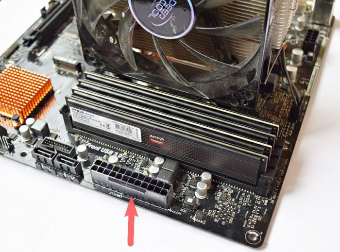
A 24-pin power supply cable provides connection to a power supply standard ATX.
He is the most right (8) in the photo below. Also in the photo are all the cables coming from the power supply.

The already outdated ATA device connector allows you to connect ATA-devices of the DMA standard type 33/66/100, and SATA - modern hard drives.
PCI-E - designed to connect video cards with the appropriate interface.
As a rule, this is a PCI-Ex16 slot.

The PCI slot allows you to add expansion cards. See photo above.
computer assembly process
Now you can start installation. And it begins with the installation in the motherboard socket of the main device - the processor.
At this stage, you need a motherboard, processor, and .
The processor has a mark on the corner that must match the mark on the socket.
To install the processor, you should “open” the contact plate, for this you need to lift up (all the way) the lever located on the contact plate, while its upper part will move slightly, freeing the contact holes.

The processor should drop into the socket without much effort.

After installation, the contact plate should be closed by lowering the lever until it clicks.

Then you can fix the radiator with the cooler and connect it to the appropriate pins.


Please note: before installing the fan, the contact surface of the fan with the processor must be coated with a special thermally conductive paste (usually supplied with the fan).

But you can also purchase separately on the radio market, for example, KPT - 8.

Installing other devices
Installation of memory modules and video cards, installation of the system board.
The RAM also has a recess slightly away from the middle of the bar, which should line up with the corresponding plug in the slot.

To mount the RAM, you need to “open” its slot by pulling the latches to the sides.
These slot latches should return to their original position when the module is installed.

It is advisable to mount the same type of pairs of memory modules in slots of the same color in order to implement the so-called. dual channel operation and get 10-15 % increase in performance.

If you are building a PC with a separate video card, now is the time to insert it into the expansion slot PCI-E.

Before installation, you should remove the plug in the back wall of your case just below the slot, so that a hole is formed in the back wall for the video card connectors to come out.
Carefully align the contacts of the card with the slot, move the slot latch slightly to the side and push the card in with a little force, and then release the latch.

If your card is of high power, it is powered not through the slot, but through an additional power cable. Be sure to connect it to the connector on the system board.

The system board can now be installed in the chassis. Modern cases have, as a rule, built-in special mounts for the motherboard.
Align the mounting holes on your motherboard with the corresponding mounting holes on the case.
If under part of the holes for mounting the motherboard there are no corresponding attachment points on the case, that is, the motherboard seems to be “hanging in the air”, special plastic stops must be inserted into such holes.
After that, fasten it with screws to the corresponding mounting points of the case.

Now you can connect the power cable coming from the power supply, its connector is also unique, so you will not be able to mix up the power polarity.

Connecting external drives
Magnetic disks store all PC information and the operating system that is loaded from the disk at startup. Protect discs from mechanical damage, shock, shock.
When moving the system unit over long distances, it is better to remove the hard drive and move it separately.
There are two standards for connecting external drives, that is, magnetic and optical drives - the old ATA or PATA interface and the new one.
The new one differs from the old in convenience and speed. But PATA devices are still found, so let's consider both interfaces.
To connect you need a special data cable.
It must be connected to the disk with the side that has the inscription " MASTER". Connector labeled " SYSTEM» is connected to the system board.
Very often there are no inscriptions on the train. Then you should remember that the connector " MASTER» corresponds to the end of the loop that has the 3rd intermediate connector « SLAVE"Designed to connect a slave (auxiliary) drive or optical drive.

Thus, two ATA devices can be connected with one cable.
All PATA drives have switches (jumpers) that should be set in accordance with the "MASTER" or "SLAVE" mode.

After connecting the cable to the drive, install it in the slot in the front of the case and secure with screws. Then connect the power to the drives with a 4-pin connector coming from the power supply.


The SATA interface is simpler and more convenient, there are no jumpers, and a thin cable does not restrict the ventilation of the case.
On the system board, the SATA connectors are usually placed at the bottom right.

The power supply is also different.

Optical drives are connected in the same way. Usually a DVD-RW drive is installed.
Old connection interface.

New connection interface SATA.

After connecting the data cable, install the DVD drive into the case and fix it with four screws. We connect the power cable.
Then you need to connect the cables of the power button, hard reset button and various indicators of PC operation.
Their connection is described in detail in the instructions for the motherboard.

Check that all boards and disks are installed without distortion. Put on the case cover (to the right of the front panel) and fix it with screws.
Put on the left cover and fix it with screws.
At this stage, the assembly stage of the PC system unit is completed.
The remaining components and devices (peripheral devices) are connected to the system unit through the appropriate connectors located on the rear wall of the unit, for example,.

Also, to improve the cooling system, additional fans can be installed in the system unit.

We examined the main stages of self-assembly of a computer.
Approximately you should get something like this.

As a rule, if the components are selected correctly, no problems should arise and the assembly process will take a maximum of 30 to 60 minutes.
Well, in the future you will need, or some other.
But that's another story. Follow the link above. Good luck.
I would be grateful if you share this article on social networks:Hello friends! If you are a computer enthusiast, then learn by yourselfassembling a computer will not be difficult for you.
When I wrote this article, I immediately showed it to a person who had never assembled a personal computer. He read it carefully and began to ask me questions, from which I realized that the publication needed to be urgently supplemented with a lot of little things, only then it would become understandable to beginners, as a result, I almost completely rewrote the article several times, and only now I offer it to your court.
In my last publication, I explained to you, but today we will independently produce a classic PC assembly.It is best to assemble a computer on a table so that you can see everything and as conveniently as possible. Let's start withapplying thermal paste to the processor and installing it in the motherboard socket, then compose the processor cooler and connect it, after that we insert RAM modules into special connectors on the motherboard, then we mount the power supply unit into the case and tighten the wires, fix the SSD, HDD in the system unit, and only after that we install the motherboard into the case ...
First, we need to buy thermal paste and apply a thin layer on the processor. It is inexpensive and is usually sold together with a special hard card, with the help of which, literally, it is smeared on the surface. Why do you need thermal paste? During operation, the processor becomes very hot and with the help of thermal paste effectively removes heat from itself to the cooling radiator.


Installing the processor on the motherboard
Now install processor in , in my case i5 6400 and Asrock z170m pro4s. It is worthwhile to install the processor into the socket very carefully and carefully so as not to damage it. In particular, this applies to AMD processors, since, unlike Intel processors, which have contact pads, first there are so-called "legs", bending which the processor will stop working. So, we open the socket socket on the motherboard using the side latch and look at the keys that show us how to insert the processor correctly.


We take the processor in our hands and see that it has the corresponding recesses, and a triangle in the corner, thanks to which it will be difficult to make a mistake during the installation process.

With a gentle movement of the hand, we simply put the processor into the socket,

We make sure that it does not hang out there and close the side latch.

CPU cooler
Further, I prefer to equip the motherboard in full and install the RAM on it immediately, outside the case, because it is problematic for me personally with my big hands to do this in a cramped space (inside the case).
So, we look at the motherboard and see special connectors for mounting the cooler, that's where we will put it with you.


This is done simply, we take the cooler, get into the holes with special legs and snap them into place.

After installation, everything will look like this.


Do not forget to also connect the power supply of the cooler to a special connector on the motherboard called CPU FAN.


RAM
Power Supply
Now that the motherboard is fully charged, we move on to installing it in the case. Many people advise installing the motherboard in the case first, but I prefer and recommend that you start with a PSU, because if you follow my advice, you can stretch all the necessary wires properly and avoid damage to the mother, since the unit is usually very large and takes up a lot of space . One awkward movement and you can easily damage the chips - goodbye motherboard. In my case, a GMC Forge case and an Aerocool KCAS 600W PSU.
Installing the unit is a very simple process. We put, we stretch the wires as we wish and we twist the screws into special holes on the back of the case.


I want to note that the power supply is always installed in such a way that the fan is directed downwards when the unit is bottom mounted. Inside the case, you can tell your own microclimate and your own temperature, so it would be better if the power supply draws in cool air from the outside, and not warm air from the inside.
Solid state drive SSD and hard drive
Now before installing the motherboard for the same reason, similar to the power supply. We insert the solid state drive and the hard drive into the appropriate baskets, if they are, if they are not, then we simply fasten them to the case. I will have a Patriot Spark 128gb and a Seagate Barracuda 7200 1000gb working hard on my system.


Motherboard
Let's move on to installing the motherboard in the case. On the mother itself there are special holes for mounting, depending on the model, the number of these holes may vary. We insert the motherboard into the case in accordance with these fasteners and tighten with screws, which must be included with the case.


Processor power
And finally, it remains for us to connect all this stuff together. Let's start with the processor power. The power connector is 4pin and 8pin and is usually located directly next to the processor. We find the appropriate cable at the power supply and connect it.


Motherboard power


Case cooler
Let's move on to connecting case coolers for blowing / blowing. They are connected to the corresponding connectors on the motherboard with the name CHA FUN or SYS FAN or similar.


Now let's connect our drives with SATA interface cables to the appropriate slots on the motherboard.
Do not forget to connect additional power to our drives. In my case, this can be done from the back of the case.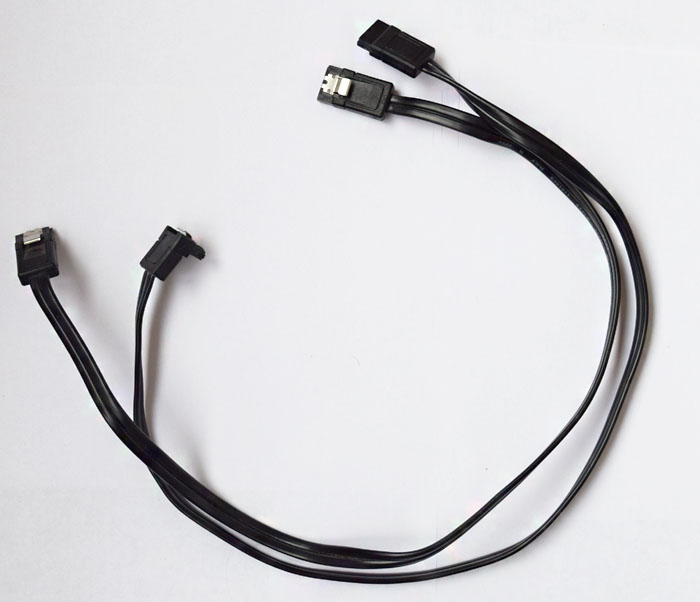

The first thing to understand is why you need such a system. Not only the cost of assembly depends on this, but also the nature of the choice of components. The most common computer that performs standard tasks can be assembled from entry-level elements. There is even an opportunity to play low-cost games. If you are an avid gamer or are demanding on graphics, then this choice is indispensable. You need a so-called gaming computer. You will need more RAM (from 16 GB), a processor with at least 4 cores, one or two discrete graphics cards, and, of course, a powerful power supply that will pull it all. The price of this pleasure can exceed 100 thousand rubles. Is it worth pursuing this? Everyone decides for himself. But it is more expedient to opt for a mid-range car.
What do you need to assemble a computer
CPU
The “heart” of a computer is considered to be the CPU, on the power of which a lot depends - whether an external video card will show its full potential, whether it will be possible to open several resource-intensive applications at once, whether it will be comfortable to watch videos in UltraHD format. For these purposes, Intel processors (i5 or i7) are suitable. The clock frequency starts at 3 GHz. It should not be surprising that in 10 years this parameter has increased insignificantly. Engineers have achieved a reduction in the technological process, which made it possible to increase the number of transistors on a chip, reducing power consumption.
It is better to pay attention immediately to the seventh generation of Intel processors, since the graphics card built into them allows you to play video content in the H.265 format, which is gaining popularity. The latest generation codec supports not only high frame rates, but also 10-bit color. A dual-core processor with four Pentium threads, the cost of which is minimal, can currently decode such material. Therefore, such a CPU is suitable for assembling a non-gaming system. For games in FullHD format, you need to look at the i5 line, in 4K - to the i7 series.
A landmark event in 2017 was the release of competitive models from AMD. The Ryzen 7 1800X can perform on par with the Intel i7-7700k. The most powerful platform for the average user will be based on one of these "stones". But the cheapest computer on AMD Ryzen cannot be assembled, since these processors do not have an integrated video core.

CPU cooling system
During the operation of the “stone”, heat is released, which must be removed. Therefore, a fan is required. Central processors are supplied with a cooler (BOX version) and without (OEM). If you are a connoisseur of silence in the room, then it is better to choose the second option. Usually, third-party coolers have lower noise levels. For example, in the Alpine 11 PRO model from Arctic Cooling, this figure reaches 14 dB, which is 9 dB lower than that of “boxed” fans. Despite this, it is capable of cooling processors up to 95 watts. But it will not work if you are going to increase the clock frequency of the CPU specified in the specification. For a gaming system, you must opt for a cooling system with copper heat pipes. Copper base improves heat dissipation performance. For example, the TITAN Hati TTC-NC15TZ/KU cooler is designed for a maximum processor heat dissipation of already 160 watts.


Today, most cooling systems are made with speed control depending on the temperature of the CPU. When the system is not loaded, less power is required. Therefore, the fan should rotate more slowly (from 500 rpm) and create less noise. This modification has a 4-pin power connector, without control - a 3-pin.
The cooler has various mounts for AMD and Intel platforms. The most common sockets are LGA 2011 and 1151, and for AMD Ryzen processors, boards with AM4 have begun to be released. Compatibility is very important, check it in the instructions or on the manufacturer's website.
Motherboard
The foundation on which the entire system rests is called the computer motherboard. Models differ in the socket where the central processor is installed. This has been said before. In turn, they are divided according to the type of chipset, which is the link between the components. For example, Intel has Z270 or X99, AMD has X370 or 970.
The form factor also matters (ATX, mATX or mini-ITX). It depends on the type of case in which all the elements of the computer are located. An inexpensive machine can be obtained based on mATX. This motherboard has a shortened size, while retaining all the necessary functions. The gaming modification does not imply savings; the ATX type is suitable for it. For enthusiasts who need maximum performance and detailed rendering in games, manufacturers have added SLI and CrossFire functions (combining the power of several video adapters). Modern technologies allow you to install up to four video cards with one GPU. If the model name contains the word “Gaming”, be sure that it is supported here. A nice addition would be the presence of a backlight.
The backplane contains two or four RAM slots. For the future, it is better to purchase with four, so that later you can increase the total amount of memory. It is more profitable to choose a platform that supports DDR4 memory, the price of which is equal to DDR3. Check compatibility on the manufacturer's website.
If the video is built into the CPU, you need to pay attention to which outputs are used to communicate with the monitor. HDMI and DVI interfaces are common.
There are also USB ports on the back panel. At the moment, their fastest type is USB 3.1, including the input for various gadgets - Type-C.

All modern boards have PCI-E 3.0 x16 slots.
The audio controller will be essential for music lovers or movie lovers with high quality sound. We choose the most effective ones - SupremeFX S1220 or Realtek ALC1150/1220. Digital audio has better performance than analog. Therefore, manufacturers began to include an optical S/PDIF connector. An audio device with an HDMI input can be connected through the corresponding video card output.
The power supply of the motherboard and processor must be 24 + 8 pin.

RAM
Previously, its volume was measured in megabytes. Now even 4 GB is not enough. Memory sticks are located in slots on the system board. Some applications and, especially, games require large resources. The minimum required amount can be considered 8 GB. For gamers, 16 GB is already required.
The performance of RAM increases if it works in 2 or 4 channel modes. Therefore, we choose two bars with a volume of 4 or 8 GB, depending on the needs.
The bandwidth of DDR4 is higher than that of DDR3. At the same time, the power consumption is less. If the first operates in the voltage range of 1.2 - 1.35 V, then the second - at 1.5 V.
The memory frequency is critical if the video adapter is built into the processor. Otherwise, strips with a frequency from 2133 to 2666 MHz and a voltage of 1.2 V will do. Increasing the frequency will require an increase in the supply voltage to 1.35 V, which will lead to large energy costs.
The ideal option is to purchase two sticks of 8 GB RAM with a frequency of 2666 MHz.

video card
The graphics card is an important element for transferring video information from the computer to the display. It is of two types - built-in and external. The first does not require additional power and is not intended for games. The most advanced video core in Intel processors is HD Graphics 630, which is capable of decoding high-bitrate video in H.265 format. If this suits you, then you can save a lot on assembly without resorting to an external adapter. Otherwise, you can't do without it.
It all comes down to price and performance. The market offers many options for discrete graphics cards. Their power has grown so much that none of them can do without fans, the number of which reaches three. Another important parameter appears - the noise level.
Two manufacturers are fighting for a buyer in this segment - NVidia, which is more productive and colder, and AMD - a balance of price and quality.

For the average user, for whom the availability of online games is the maximum requirement, a model from NVidia's junior line, the GTX 1050TI, is suitable. It is equipped with a sufficient amount of 4 GB video memory, the recommended power supply is only 300 watts, it supports a high resolution of 7680 x 4320.
Fans of high-end games need a more powerful video adapter. They have the following models to choose from - GeForce GTX 1060, GTX 1070, GTX 1080, GTX 1080TI and GTX Titan X. The latter has 12 GB of the fastest GDDR5X memory, but requires 250 watts of power. GeForce GTX 1080 with 8 GB of VRAM and 180 watts is the best option for gaming in 4K resolution in the highest detail. If you are comfortable playing with medium settings, then choose the GTX 1070 from the price / performance ratio.
To improve energy efficiency in some models, cooling systems in idle mode are able to stop the rotation of the fans to reduce noise. The use of two or more coolers increases the reliability of the video system as a whole in case of failure of one of them.
Information carriers
Any computer cannot do without hard drives, which will store personal data or install an operating system. For faster loading and running Windows, you will need at least a 120 GB SSD drive. It consumes less power than a mechanical disk, is silent and takes up less space in the case. But he is not without flaws. The main ones are the time between failures and the higher price. Therefore, if you are recording a large amount of information, it is cheaper to buy an internal or external hard drive with a size of 4 TB or more.


Power Supply
When all the components of the PC platform are selected, let's start looking for the most important element on which the stability of the system depends. The power supply is involved in the distribution of energy and stabilization of the mains voltage.
If you have an office version of the computer (for example, without an external video card), then 400 watts of power will be enough. The average video adapter will require a 500-watt PSU. To power a GTX Titan X or multiple devices in SLI/CrossFire mode, you need a 750-watt unit.
There are two main indicators - efficiency and PFC. More efficient are power supplies with an efficiency of more than 80% (standard 80 Plus). How much useful energy is transferred to PC components depends on the efficiency. The larger it is, the less the power unit heats up. It is recommended to use a PSU with active power factor correction (APFC), as it further smoothes the voltage supplied to it. But it has a significant drawback - this type of device does not involve the use of uninterruptible power supplies (UPS).
For more information about choosing a power supply, see the article choosing a power supply for a computer.

Frame
All elements of the future system are placed in a metal box. The thicker the sheet, the more reliable. By size, they are divided into ATX, mATX and mini-ITX. The choice is yours. Small cases have limited volume for good ventilation, but take up less space. The ATX size allows you to install a long video card.
A case with a transparent cover will look spectacular, where you can see the LED backlight inside. Expensive models are supplied with an additional cooling system. This is important for a gaming PC that experiences intense heat.
It is better to choose the lower location of the power supply, as it takes cold air from under the bottom.

Peripherals
But the choice is not over yet. Without input manipulators, it is impossible to use a computer. The mouse and keyboard are wired (USB and PS / 2) and battery-powered. The second option is more practical, but the communication signal sometimes disappears. It's cheaper to buy a set. For a gaming PC, a mouse with multimedia buttons or a gamepad is suitable.
If there is a need to record information on optical media, then we purchase any DVD-RW drive.
Finding a monitor is a separate issue. We only note that you need to select displays on LEDs, flicker-free and with the ability to reduce blue radiation. It is recommended to check the viewing comfort in the store, as TN + film, IPS and VA matrices differ in contrast and color reproduction. Otherwise, the difference is only in resolution and diagonal.
How to assemble a computer yourself from components
PC components purchased. You can proceed directly to the assembly.
We take the motherboard out of the box and place it on cardboard or foam rubber. We find on the board the socket for installing the CPU. We take the processor and carefully insert it there without any additional effort.

The CPU cooler comes with thermal paste. We smear it with a thin layer on the surface of the “stone”. After reading the instructions, install the propeller on the base of the board. We check the tightness of the bases to each other. Connect the cooler power wires to the “CPU_Fan” connector. We find a similar connector for connecting a case fan.


We place the power supply in the case, which is fastened with screws.

In front of the case on a metal rack, we fix the existing hard drives, SSD drives and drives.

Before installing the motherboard, we screw special legs into the holes in the case to prevent short circuits.

The backplane is included with the backplane for connectors of external parts of the PC: monitor, speakers, USB devices.

Carefully place the board on the legs and fasten with screws.


We remove the plug at the back of the case and insert a discrete video card into the PCI Express x16 slot.


It's time to connect all the installed elements with cables.
We connect the plugs on the front panel of the case - indicators of hard drive operation and power availability, buttons to restart and turn off the PC, as well as for USB ports. The connectors are usually located in one place under the PCI slots and are labeled.


We connect hard drives and disk drives to the system board with SATA cables.

It's time to start connecting the components to the power supply. First, we insert a 24-pin (or 20 + 4 pin) cable, which is responsible for supplying power to the motherboard, then an 8-pin cable that feeds the CPU.


Let's supply power to the devices for recording and storing information.


An external video accelerator usually requires additional power. We look for this wire from the PSU (6 and 8-pin) and insert it into the connector on the device.
Building a computer from scratch is complete. We close the case with a lid. We connect the monitor with a wire for transmitting video data, plug the network cable into the PSU, and the mouse and keyboard into the corresponding USB or PS / 2 ports. We turn on the computer.
Important steps in assembling a PC are determining the functions that it will perform and calculating the power of the power supply. This will help save a lot of money. Next, find out if an external video card is needed. She's not cheap either. SSD drives are a necessary element for maximum system performance. Efficient cooling in the case will require an additional fan. If the motherboard and graphics card have LED backlighting, then it is advisable to choose a frame with a window on the side wall. The main advantage of assembling with your own hands is the ability to replace components at any time.
3DNews has a large and diverse audience. The resource is visited by both seasoned enthusiasts who have assembled far from one PC, and readers who are just starting to delve into all the intricacies of computer technology. The test lab elegantly overclocks them to serious frequencies, to study the durability of drives, in modern games and to purchase unusual hardware abroad, but at the same time, it does not forget about inexperienced users. So the heading "" appeared, which offers a variety of configurations of system units. After reading the comments and personal communication with the readers of the site, it became clear to me that it was time to tell in detail and show newcomers how to assemble the components proposed in the article into a single whole. This is what this article is about.
⇡ Selection and compatibility of components
Sometimes it’s harder to decide on a set of components that will make up your PC than to assemble a system unit at home with your own hands. On sale you can find a huge number of processors, motherboards and video cards. You can argue for a long time about which brand is preferable, as well as discussing whose graphics are faster - the main thing is that when you finalize the configuration, all hardware is fully compatible with each other. By the way, it is precisely such systems that I offer in "". Subject to this rule, the assembly of the system unit is not much different from the game of constructor, in which all the parts fit together. Component sizes, mounting hole parameters and connectors - all computer elements are strictly regulated, and therefore, for example, it cannot be that DDR3 RAM suddenly works on a motherboard with DIMM slots designed to install exclusively DDR4 modules. You simply cannot install them in the appropriate slots.
For the full functioning of the system unit, you must purchase the following devices: motherboard, central processor, cooler, RAM, hard drive or solid state drive, video card (if the CPU or motherboard does not have an integrated graphics core), power supply and case. Additional components include an optical drive, as well as all kinds of discrete devices: network and sound cards, additional cooling.

The motherboard is the backbone of any computer. It depends on it which processors will be used, how many RAM modules, video cards and drives can be installed. Motherboard dimensions also play an important role in case selection. At the moment, among motherboards, solutions of the form factors E-ATX (305 × 330 mm), ATX (305 × 244, 305 × 225 or 305 × 199 mm), mATX (244 × 244, 244 × 225 or 191 × 188 mm) and mini-ITX (170 × 170 mm), although there are much more standard sizes of such devices. The form factor is always listed in the chassis specifications.
The “home” for components itself is also divided into types depending on the size and shape. As a rule, the larger the computer case, the more productive hardware we can install in it, while ensuring high-quality cooling of all system components. Dependence, however, is non-linear - practice shows that it is quite possible to assemble a powerful gaming PC in compact cases with a volume of 7-10 liters. You just have to carefully select all the components first.
Among PC cases, four types of models are most popular: Midi-Tower (examples - and), Full Tower (), Mini-Tower () and Slim Desktop (). Naturally, the smaller the device, the fewer seats it has for installing discrete video cards, drives, and case fans. For example, the Node 202 with a capacity of 10 liters can only install 2.5-inch hard drives and SSDs. A conscientious manufacturer indicates all these features in the technical characteristics of the device.
When choosing components, pay attention to other limitations that any computer case has:
- maximum height of the CPU cooler;
- maximum length of the video card;
- maximum length of the power supply.
Before buying equipment, be sure to make sure that all devices are compatible with each other, do not conflict and fit exactly in the computer case. The simplest logical chain that will not allow you to purchase components that do not match each other is as follows:
- We determine the model of the central processor.
- We select a motherboard with a suitable socket for this CPU.
- We study the list of compatible motherboard hardware on the official website and select a set of RAM.
- Choose drives that are compatible with the motherboard.
- We select a video card, power supply, processor cooling and a case that will fit all the components.
Again, the above sequence is by no means an axiom. Since building a PC is always a creative process, the sequence of choosing hardware can change. For example, you liked a certain case and want to assemble your dream system only in it. Or do you already have some components on hand, and you need to buy everything else.

If the system unit will use an unattended water cooling system for a processor or video card, then it is additionally necessary to find out the sizes of supported radiators, as well as the places where they can be installed. It is obvious that the seats for installing the SVO coincide with the places where the fans are attached. Single-section radiators are usually installed on the rear wall, two-section and three-section - on the top and / or front.

To write this material, based on the above sequence for selecting components, I used the following set of devices:
- AMD Ryzen 7 1700 CPU, socket AM4, 3.0 (3.7) GHz;
- MSI X370 GAMING PRO CARBON motherboard, socket AM4, X370 chipset;
- RAM Kingston HyperX Fury (HX426C16FR2K4 / 32), 4 × 8 GB, DDR4-2666;
- solid state drive;
- video card;
- power supply Cooler Master MasterWatt, 500 W;
- case Cooler Master MasterBox 5 MSI Edition;
- processor cooling Cooler Master MasterLiquid 120.
As you can see, in preparing this material, the most common form factors are used - ATX for the motherboard and Midi-Tower for the case. Similar options are offered in the "Computer of the Month" - because this size is the most versatile and most popular. True, I cannot say that the assembly process in Mini-Tower and Slim Desktop cases is fundamentally different. It's just that the requirements for the selection of iron compatible with each other turn out to be much higher.
In addition, I note that when selecting devices, all modern trends are taken into account. The main drive is the Kingston HyperX Predator model with a PCI Express interface. And the choice in favor of Cooler Master MasterBox 5 MSI Edition was made because of the possibility of installing a power supply unit in the lower part of the chassis, as well as the presence of a mount for drives on the barrier wall. Plus, maintenance-free liquid cooling systems are very popular. Cooler Master MasterLiquid 120 is a bright representative of one-section dropsies, which are ready to work out of the box. The remaining components are selected in such a way that in the end we get a productive system unit for work and entertainment. The optical drive has not been used. In my opinion, in 2017 there is no need for it, and the Cooler Master MasterBox 5 MSI Edition (as well as many other new cases of this format) lacks seats for installing devices in 5.25-inch bays.

To assemble the system unit, you will definitely need two Phillips screwdrivers with different slot diameters, nylon ties and wire cutters. Pliers may come in handy - in cheap cases, threads are cut by eye, as well as double-sided adhesive tape, degreasing liquid and cotton swabs. In order not to scratch the case and not damage the motherboard, I put all the components on a rubber mat. An anti-static wrist strap or gloves are also useful for beginners, but, to be honest, more to give self-confidence. Since assembling a PC includes connecting small connectors to the motherboard, you definitely cannot do without good lighting or a flashlight at hand.
⇡ Step #1. Installing the processor and RAM
The motherboard user manual always contains a description of the installation of all major components and connectors. Beginners, keep this book with you. The sequence of steps for assembling the system unit may vary depending on the type of components. For example, sometimes it is better to install a processor cooler immediately, and sometimes - in the penultimate or last place. Even before fixing the motherboard in the case, you must install the CPU and RAM in the appropriate sockets.

You probably know that AMD and Intel processors are structurally very different from each other. So, for AMD chips, protruding contacts, called “legs” by the ironworkers, are located directly on the textolite substrate. But Intel chips do not have such elements - for these CPUs, the contacts are placed directly in the motherboard socket.
AMD chips are installed very simply: raise the lever, put the processor on a plastic substrate, lower the lever.

As for Intel solutions for LGA115X platforms, a similar technique is used here: together with the lever, we raise the clamping frame, install the processor, lower the lever and the clamping frame.

In the case of the Intel LGA2011 and LGA2011-v3 platforms, two levers must be released from the locking slots to raise the clamping frame.
|
|
|


Please note that all CPUs and motherboards are equipped with pointers and so-called foolproofing. In principle, you will not be able to install the chip into the socket in any other way, so NEVER use force when assembling a computer. All elements in the system unit are equipped with protection against incorrect connection. In addition to the CPU, you will not be able to connect power supply cables, case connectors, fans, discrete devices, drives and RAM in any other way. More precisely, you can, but this will require maximum effort. I think it's not worth talking about the consequences of improper installation of PC components.

After the CPU, I install RAM into the DIMM slots, usually located on the right side of the CPU. MSI X370 GAMING PRO CARBON supports DDR4 RAM, four ports are soldered on the printed circuit board at once. In some motherboards, there may be only two of them (most often these are either the cheapest devices, or mini-ITX form factor solutions, or), in models for the LGA2011 and LGA2011-v3 platforms, eight. Usually on PCB all DIMM slots are marked.
Most modern AMD and Intel processors have dual-channel RAM controllers. Therefore, motherboards use either two or four DIMM slots. Therefore, the installation of either two or four RAM modules is considered optimal. In the first case, RAM is installed through one connector. Some motherboards have special pointers. For example, in the MSI X370 GAMING PRO CARBON, modules are installed in the DIMMA2 and DIMMB2 slots - in this case, the RAM will work in dual-channel mode. In other motherboards, there are inscriptions like - in such cases, to ensure the operation of the dual-channel mode, the modules must be installed in the DDR4_A1 / DDR4_B1, DIMM_A1 / DIMM_B1 and DDR4_1 / DDR4_2 slots, respectively.

"Fool-proof" in RAM
I have already said that it will not work to insert the RAM incorrectly, since a jumper is used in the design of the DIMM connectors. It is also used to prevent the user from "squeezing" modules of another standard into a motherboard that supports DDR4.
RAM boards are fixed using latches located along the edges of the DIMM slots. On some motherboards, these latches are located on only one side of the connectors. This is done so that the user can freely change RAM modules without removing, for example, a video card.

After installing the CPU and RAM, you can immediately install a CPU cooler, but only if its design uses a small heatsink. The use of an overall cooling system will make it difficult to install the motherboard, as well as the subsequent connection of wires. The photo above shows examples of installing boxed coolers - the so-called COs that are sold together with processors. Coolers for AMD AM3+ and FM2+ platforms are attached using plastic "ears" - a special metal bracket with lugs clings to them. Boxed cooling for Ryzen chips is installed differently, here you have to work with a screwdriver: first remove the plastic mount, and then screw the heatsink to the backplate. The cooler for Intel processors is attached using plastic clips: install the heatsink on the CPU and press the latch until you hear a characteristic click. In general, in the case of installing boxed cooling systems, even beginners should not have problems.
Some coolers already have thermal paste on the soleplate - its use significantly increases the efficiency of heat removal from the CPU. In any case, thermal paste is always included with the CPU cooler. For example, Cooler Master MasterLiquid 120 came with a small tube, which, nevertheless, should be enough for 3-4 times. Please remember to remove the protective film before installing the cooling system, if any, on the base of the device. The process of applying thermal paste is described in paragraph number five.
But the installation of other coolers is carried out on an individual basis, since each manufacturer uses a fixing kit of his own design. Therefore, immediately take out the instructions from the packaging from the CO. Most devices are equipped with universal mounting mechanisms that are suitable for both AMD and Intel processors. True, the mating part of the mount, which must be pre-fixed on the board, is different for different platforms. The list of supported equipment, as well as the dimensions of the cooler, are always indicated in the technical specifications. And yet, there are enough models on sale that are compatible with only one specific platform.

Once again: if the device is large or, as in my case, a maintenance-free liquid cooling system is used, then at the first stage it is enough to fix the back plate and frames on the board, which will hold the cooler radiator. We will install the radiator itself in the penultimate turn, after all the cables are connected to the motherboard. Yes, in cases of the Cooler Master MasterBox 5 MSI Edition level, the barrier wall has a window for accessing the cooler's backplate, but it is far from always convenient to use it.

If we talk about air processor coolers, then the tower-type coolers are considered the most popular. Depending on the platform used and on the specific model, the CO radiator can be installed in two positions. In the first case, the cooler fan will blow air through the back wall of the case, in the second case, through the top. The correct installation option determines the shape of the enclosure used. So, in the case of models of Full-, Midi- and Mini-Tower formats, it is better to use the first option. It is important that the CO used does not overlap the expansion slots, and also does not rest against the cooling elements of the motherboard power subsystem. For example, MSI X370 GAMING PRO CARBON does not conflict with even the largest cooling towers. Also, a wide CPU cooler can interfere with the installation of RAM modules with tall heatsinks. Therefore, it is better to use compact RAM kits, such as the Kingston HyperX Fury for example, or make 100% sure that CPU cooling and memory will not conflict with each other.
Our build uses the maintenance-free Cooler Master MasterLiquid 120 liquid cooling system, so it will be installed last but one (step #5).

Cooler and case fans are connected to the motherboard using 3- and 4-pin connectors. The MSI X370 GAMING PRO CARBON has six such elements soldered at once, which is very convenient. The number of such ports is not regulated in any way, but at least two connectors must be present on the board: for connecting a CPU cooler fan and for a system (case) impeller. All connectors are marked accordingly: CPU_FAN, SYS_FAN (or CHA_FAN). Sometimes a 4-pin connector designed for a processor cooler is highlighted in a different color (most often white). And in the boards of the middle and high price ranges, you can find the PUMP_FAN connector. It is designed to connect the rotor of a water cooling pump, but at the same time it is suitable for any other fans. It's just that a larger current is transmitted through this port.
The connector with three pins does not allow you to adjust the speed of the fan connected to it. But the 4-pin port has such an opportunity, and modern motherboards can control the speed of the “turntables” both with pulse-width modulation (fans with four pins) and without it (fans with three pins).
With a shortage of connectors for connecting case fans, all kinds of adapters will help. This can be an ordinary splitter that allows you to connect several impellers to one 3- or 4-pin port at once. Or a cable connected to the MOLEX or SATA connector. And there are devices such as, although their popularity has never been high. However, they are initially equipped with simple (most often three-position) controllers that control the fan speed by lowering the voltage from 12 to 7 or 5 V.
In the case of our PC, there is no need for additional adapters and splitters, since only two CBO fans and one case impeller need to be connected to the motherboard.
⇡ Step #2. Installing the Motherboard and Connecting the Case Connectors
Now that the CPU and RAM are connected to the motherboard, it's time to start working on the case.

For a long time, in tower cases, the power supply is installed mainly from below. This was done both for aesthetic reasons (it is more convenient and easier to lay wires), and for the sake of increasing the cooling efficiency, primarily of the PSU itself. However, on sale there are models of cases with other options for installing a power supply unit.

Seats for installing the power supply, 2.5- and 3.5-inch drives
The Cooler Master MasterBox 5 MSI Edition is designed with a small sled cage that holds two 3.5-inch hard drives. More compact 2.5-inch drives are mounted on a barrier wall.

Installing the motherboard begins with securing the I/O panel blank in the rectangular hole provided for this purpose. You won't have any difficulties. The plug is always included with the motherboard.

Mounting accessories are always supplied with the housing. Along with the Cooler Master MasterBox 5 MSI Edition, I found three types of screws, as well as plastic clips for installing additional fans. Other housings may have more mounting options. On some models, the standoff screws needed to mount the motherboard are already screwed into the corresponding threaded holes on the barrier wall. In the case of Cooler Master MasterBox 5 MSI Edition, you will have to do this procedure yourself.

So, the case supports the installation of mini-ITX, mATX, ATX and even E-ATX form factor motherboards. There are symbols on the wall (a similar memo is used in many models). Since the assembly uses an ATX form factor board, it is necessary to screw all eight stand screws into the threaded holes marked with the letter "A". However, not all motherboards related to this size correspond to the length and width parameters of 305 × 244 mm. For example, the MSI X370 GAMING PRO CARBON is already 19 mm, so it cannot be fixed in the case along the right edge. Therefore, when connecting wires from the power supply or mounting memory modules in DIMM slots, the PCB will sag. Install these items carefully in such cases.

After the motherboard is fixed, I personally immediately connect the controls and connectors of the front panel of the case. On the front wall of the Cooler Master MasterBox 5 MSI Edition, there are two USB 3.0 A-type ports, two 3.5 mm mini-jacks for headphones and a microphone, as well as system power and forced reboot keys. Difficulties can arise only when connecting controls - this is a bundle of wires with Power LED- and Power LED + connectors (transfer information to the computer status indicator), Power SW (responsible for the operation of the power key), HDD LED- and HDD LED + (transmit information to the drive activity indicator ), as well as Reset SW (responsible for the operation of the forced reboot button). Some elements may not be on the “face” of the case, since not all devices are equipped, for example, with a Reset key or LED indicators. However, in all cases, these connectors are connected in a certain sequence, as shown in the table below. It's just that motherboard manufacturers use their own designations for essentially the same pad: JFP1 in MSI motherboards; PANEL at ASUS; PANEL1 on ASRock and F_PANEL on GIGABYTE.
| Power LED+ | Power LED- | Power SW | Power SW |
| HDD LED+ | HDD LED- | Reset SW | Reset SW |
In addition, among the internal connectors on the motherboard, there may be contact pads for connecting USB 3.1 and USB 2.0 ports, RGB strips, a TPM module, FP audio, and a speaker.