Gas pressure regulators RDG-25-N(V); RDG-50-N(V); RDG-80-N(V); RDG-150-N(V)
The hydraulic mode of operation of the gas distribution system is controlled by gas pressure regulators (RDG), which automatically maintain a constant pressure at the point of impulse selection, regardless of the intensity of gas consumption. When the pressure is regulated, the initial over high pressure to a final lower one. This is achieved by automatically changing the degree of opening of the throttling body of the regulator, as a result of which the hydraulic resistance to the passing gas flow automatically changes.
Depending on the maintained pressure (the location of the controlled point in the gas pipeline), gas pressure regulators (RDG) are divided into gas pressure regulators upstream and downstream. In hydraulic fracturing (GRU), only gas pressure regulators are used after themselves.
The automatic gas pressure regulator (RDG) consists of an actuator and a regulating body. The main part of the actuator is a sensitive element that compares the signals of the setpoint and the current value of the regulated pressure. The actuator converts the command signal into a control action and into the corresponding movement of the movable part of the regulatory body due to the energy of the working medium (this can be the energy of the gas passing through the gas pressure regulator (RDG), or the energy of the medium from an external source, electric, compressed air, hydraulic) .
If the shifting force developed by the sensitive element of the gas pressure regulator is large enough, then it itself performs the functions of controlling the regulatory body. Such gas pressure regulators (GPG) are called direct acting pressure regulators. To achieve the required accuracy of regulation and increase the permutation force between the sensitive element and the regulatory body, an amplifier command device (sometimes called a pilot) can be installed. The meter controls the amplifier, in which, due to extraneous influence (energy of the working medium), a force is created that is transmitted to the regulatory body.
Since gas is throttled in the regulatory bodies of pressure regulators, they are sometimes called throttling.
Due to the fact that the gas pressure regulator is designed to maintain a constant pressure at a given point in the gas network, it is always necessary to consider the automatic control system as a whole "regulator and the object of regulation (gas network)". The principle of operation of gas pressure regulators (RDG) is based on regulation by the deviation of the regulated pressure. The difference between the required and actual values of the regulated pressure is called the mismatch. It can occur as a result of various excitations either in the gas network due to the difference between the gas inflow into it and the gas withdrawal, or due to a change in the inlet (before the regulator) gas pressure.
The correct selection of the gas pressure regulator should ensure the stability of the regulator-gas network system, i.e., its ability to return to its original state after the disturbance ceases.
Gas pressure regulators RDG with nominal bore Du-50, Du-80, Du-150 hereinafter referred to as regulators that provide reduction of high or medium pressure, automatic maintenance of outlet pressure at a given level, regardless of changes in flow rate and inlet pressure, automatic shutdown of gas supply when emergency increase or decrease in output pressure in excess of allowable setpoints. Designed for installation of hydraulic fracturing and GRU of gas supply systems of cities and towns.
The operating conditions of the regulators must comply with the climatic use UHL4 in accordance with GOST 15150-69 for operation at temperatures environment from +1°С to +40°С.
The regulator complies with the requirements of GOST 12.2.007.0-7; GOST 11881-76 and during operation does not have a negative impact on the environment.
The regulator is manufactured in two versions:
With outlet low pressure (N)
With outlet high pressure (B)

Designations of regulators when ordering in other documents:
Gas pressure regulator RDG-50N - TU 3700-003-137517595-2004
Gas pressure regulator RDG-50V - TU 3700-003-137517595-2004
Gas pressure regulator RDG-80N - TU 3700-003-137517595-2004
Gas pressure regulator RDG-80V - TU 3700-003-137517595-2004
Gas pressure regulator RDG-150N - TU 3700-003-137517595-2004
Gas pressure regulator RDG-150V - TU 3700-003-137517595-2004
If necessary, indicate the diameter of the saddle, then the entry when ordering is as follows:
Gas pressure regulator RDG-50N TU 3700-003-137517595-2004 saddle 35.
Gas pressure regulator RDG-50V TU 3700-003-137517595-2004 seat 35.
Specifications regulators RDG
|
Parameter |
||||||
|
Controlled environment |
natural gas according to GOST 5542-87 |
|||||
|
Inlet pressure range, MPa |
||||||
|
Outlet pressure setting range, kPa |
||||||
|
Maximum throughput, m³/h, not less than |
||||||
|
Uneven regulation, % |
||||||
|
Actuation pressure of the control mechanism, MPa: |
||||||
|
when output pressure drops |
(0.15-0.5) Рout |
|||||
|
when output pressure rises |
(1.25-1.5) Рout |
|||||
|
at Pout=0.003 MPa |
||||||
|
Seat diameter, mm |
||||||
|
Diameter of the inlet and outlet connecting pipe, mm |
||||||
|
Compound |
flange according to GOST 12820-80 |
|||||
|
Overall dimensions, mm |
||||||
|
Construction length, mm |
||||||
|
Weight, kg |
||||||
|
RDG throughput table |
||||||||||||
|
RDG-50N (saddle 30mm) |
RDG-50V (saddle 30mm) |
RDG-50N (saddle 35mm) |
RDG-50V (saddle 35mm) |
RDG-50N (saddle 40mm) |
RDG-50V (saddle 40mm) |
RDG-50N (saddle 45mm) |
RDG-50V (saddle 45mm) |
RDG-80N (saddle 65mm) |
RDG-80V (saddle 65mm) |
RDG-150N (saddle 98mm) |
RDG-150V (saddle 98mm) |
|
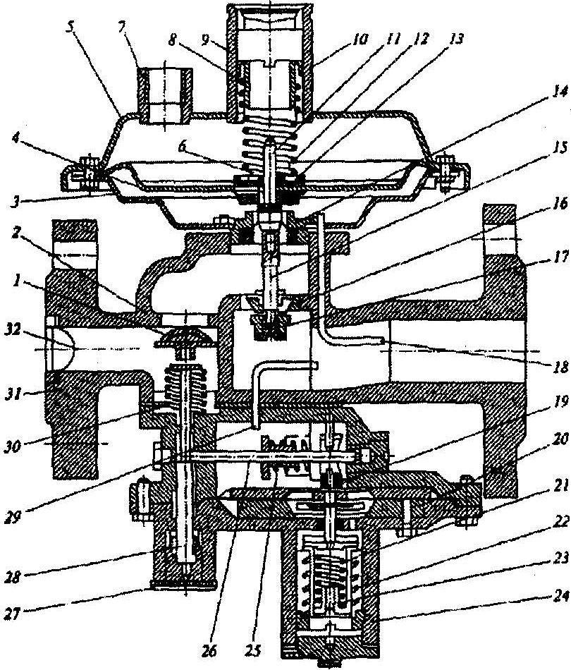
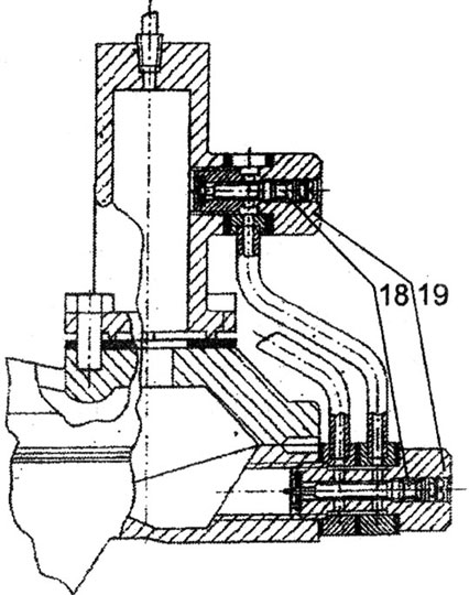
The RDG gas pressure regulator is manufactured in two versions: RDG-V (Fig. 2) consists of an actuator 2, a control regulator 15 and a control mechanism 12. RDG-N (Fig. 1) consists of an actuator 2, a stabilizer 16, a control regulator 15 and the control mechanism 12. The principle of operation is considered on the example of the RDG-N regulator. Actuator 2 has a cast body, inside of which a seat 3, a membrane drive and a valve 4 are installed. The membrane drive consists of a membrane 6, a rod 5 rigidly connected to it, at the end of which a valve 4 is fixed. The rod 5 moves in the bushings of the guide column of the body. The actuator is designed by changing the flow area between valve 4 and seat 3 to automatically maintain the specified output pressure in all gas flow modes, including zero. Stabilizer 16 is designed to maintain a constant pressure at the inlet to the control regulator, i.e., to exclude the influence of inlet pressure fluctuations on the operation of the regulator as a whole, and is installed only on low pressure regulators RDG-N. The pressure on the pressure gauge after the stabilizer must be at least 0.2 MPa (to ensure a stable flow rate). The stabilizer is made in the form of a direct-acting regulator and includes a housing, a spring-loaded membrane assembly, and a working valve. The control regulator 15 generates a control pressure for the submembrane cavity of the actuator in order to move the control valve. The control regulator includes a head and a membrane chamber. The head has an inlet and an outlet. The upper chamber has a threaded hole for supplying an output pressure pulse. The high-pressure control regulator uses a stronger spring, bearing washer, and a smaller footprint bottom cap.
Adjustable chokes 8 in the submembrane cavity of the actuating device and on the discharge impulse tube serve to tune the regulator to a quiet (without self-oscillations) operation.
Adjustable chokes 8 (Fig. 3) include a choke 28, a slotted fitting 29 and a bolt 30. The pressure gauge is designed to continuously monitor the outlet pressure and issue a signal to actuate the shut-off valve in the actuator in case of an emergency increase or decrease in the outlet pressure above the allowable specified values. The control mechanism consists of a detachable housing, a membrane, a rod, a control mechanism 11, large and small springs that balance the effect of an output pressure pulse on the membrane.
Filter 13 is designed to clean the gas supplying the stabilizer and control regulator from mechanical impurities. The regulator operates as follows: the inlet pressure gas flows through the filter to the stabilizer 16, then to the control regulator 15. From the control regulator (for RDG-N), the gas through the adjustable throttle 8 enters the submembrane cavity, the submembrane cavity of the actuator is connected by an impulse tube 9 to the outlet regulator. Through the throttle 8 and the impulse tube 9, the submembrane cavity of the actuator is connected to the gas pipeline and the regulator. The pressure in it during operation will sometimes be greater than the outlet pressure. The supra-membrane cavity of the actuating device is under the influence of the outlet pressure. The control regulator maintains a constant pressure behind it, so the pressure in the submembrane cavity will also be constant (in steady state).
Any deviations of the outlet pressure from the set one cause pressure changes in the supra-membrane cavity of the actuator, which leads to the valve 4 moving to a new equilibrium state corresponding to the new values of the inlet pressure and flow rate, while the outlet pressure is restored. In the absence of gas flow, valve 4 is closed, since there is no control pressure difference between the above-membrane and sub-membrane cavities of the actuator. In the presence of a minimum gas consumption, a control pressure drop is formed in the supra-membrane and sub-membrane cavities of the actuator, as a result of which the membrane 6 with the rod 5 rigidly connected to it, at the end of which the valve 4 is fixed, will move and open the passage of gas through the resulting gap between the valve seal and saddle.
With a decrease in gas flow, the valve, under the influence of a changed control pressure drop in the cavities of the actuator, will reduce the passage of gas through the decreasing gap between the valve seal and the seat and subsequently close the seat. In the event of an emergency increase or decrease in the output pressure, the membrane of the control mechanism 12 moves to the left or right, the shut-off valve lever comes out of contact with the stem 11 of the control mechanism, the shut-off valve, under the action of spring 10, blocks the gas flow to the regulator. To prevent gas from entering the room where the regulator is installed, in the event of a rupture of the membrane of the stabilizer or control regulator, an organized discharge into the atmosphere through the fittings (M14ґ1) in the covers of the stabilizer and control regulator must be provided. Regulators are mounted on a horizontal section of the gas pipeline with the membrane chamber down. The distance from the lower chamber to the floor and the gap between the membrane chamber and the wall when installing the regulator in the hydraulic fracturing and hydraulic distribution unit must be at least 300 mm. The impulse pipeline connecting the regulator to the sampling site must have a diameter of DN25 for RDG-50, DN32 for RDG-80 and RDG-150.
Figure 1. Gas pressure regulator RDG-N:
1 - shut-off valve; 2 - executive device; 3 - saddle; 4 - working valve; 5 - rod; 6 - membrane of the actuator; 7 - throttle washer; 8 - adjustable chokes; 9 - impulse tube of the inlet gas pipeline; 10 - cut-off valve spring; 11 - rod of the control mechanism; 12 - control mechanism; 13 - filter; 14 - candle; 15 - control regulator; 16 - stabilizer; 17 - pressure gauge; 18 - shut-off valve lever; 19 - bracket; 20 - screw; 21 - small spring; 22 - large spring; 23 - bracket; 24 - bracket; 25 - reg. small spring screw; 26 - reg. large spring screw; 27 - bracket
Figure 2. Gas pressure regulator RDG-V:
1 - shut-off valve; 2 - executive device; 3 - saddle; 4 - working valve; 5 - rod; 6 - membrane of the actuator; 7 - throttle washer; 8 - adjustable chokes; 9 - impulse tube of the inlet gas pipeline; 10 - cut-off valve spring; 11 - rod of the control mechanism; 12 - control mechanism; 13 - filter; 14 - candle; 15 - control regulator; 18 - shut-off valve lever; 21 - small spring; 22 - large spring; 23 - bracket; 25 - reg. small spring screw; 26 - reg. large spring screw; 27 - bracket

Figure 3:
28 - throttle; 29 - fitting; 30 - bolts
Order Gas pressure regulator RDG-25-N(V), RDG-50-N(V), RDG-80-N(V), RDG-150-N(V), delivery time can be used or. Upon request, we will provide: scheme, passport, certificate, permit.
Classification.Gas pressure regulators are classified: by purpose, the nature of the regulatory action, the relationship between the input and output values, the method of influencing the control valve.
According to the nature of the regulatory action, regulators are divided into astatic and static (proportional). Schematic diagrams regulators are shown in the figure below.
Diagram of pressure regulators
a - astatic: 1 - rod; 2 - membrane; 3 - cargoes; 4 - submembrane cavity; 5 - gas outlet; 6 - valve; b - static: 1 - rod; 2 - spring; 3 - membrane; 4 - submembrane cavity; 5 - impulse tube; 6 - stuffing box; 7 - valve.
V astatic regulator membrane has a piston shape, and its active area, which perceives gas pressure, practically does not change at any position of the control valve. Therefore, if the gas pressure balances the gravity of the membrane, stem and valve , then the membrane suspension corresponds to a state of astatic (indifferent) equilibrium. The gas pressure regulation process will proceed as follows. Let us assume that the gas flow through the regulator is equal to its inflow and the valveoccupies a certain position. If the gas flow increases, then the pressure will decrease.and the membrane device will lower, which will lead to an additional opening of the control valve. After the restoration of equality between inflow and flow occurs, the gas pressure will increase to a predetermined value. If the gas flow rate decreases and the gas pressure increases accordingly, the control process will proceed in the opposite direction. Adjust the regulator to the required gas pressure using special weights, moreover, with an increase in their mass, the outlet gas pressure increases.
Astatic regulators after a disturbance bring the regulated pressure to the set value, regardless of the load and the position of the control valve. The equilibrium of the system is possible only when set value adjustable parameter, while the control valve can occupy any position. Astatic regulators are often replaced by proportional ones.
In static (proportional) regulators, in contrast to astatic ones, the submembrane cavity is separated from the collector by a stuffing box and connected to it by a impulse tube, that is, nodes feedback located outside the facility. Instead of weights, a spring compression force acts on the membrane.
In an astatic regulator, the slightest change in the outlet gas pressure can lead to the movement of the control valve from one extreme position to another, and in a static regulator, the valve is completely moved only when the spring is compressed accordingly.
Both astatic and proportional regulators, when operating with very narrow proportionality limits, have the properties of systems operating on the “open - closed” principle, that is, with a slight change in the gas parameter, the valve moves instantly. To eliminate this phenomenon, special throttles are installed in the fitting connecting the working cavity of the membrane device with a gas pipeline or candle. The installation of chokes allows you to reduce the speed of movement of the valves and achieve a more stable operation of the regulator.
According to the method of action on the control valve, regulators of direct and indirect action are distinguished. In regulators direct action the control valve is under the action of the control parameter directly or through dependent parameters and, when the value of the controlled parameter changes, it is actuated by a force that occurs in the sensing element of the regulator, sufficient to move the control valve without an external source of energy.
In regulators indirect action the sensing element acts on the control valve with an external source of energy (compressed air, water or electric current).
When the value of the regulating parameter changes, the force that occurs in the sensing element of the regulator activates an auxiliary device that opens the access of energy from an external source to the mechanism that moves the control valve.
Direct acting pressure regulators are less sensitive than indirect acting pressure regulators. The relatively simple design and high reliability of direct-acting pressure regulators have led to their widespread use in the gas industry.
Throttle devices pressure regulators (figure below) - valves of various designs. In gas pressure regulators, single-seated and double-seated valves are used. Single-seated valves are subjected to a one-sided force equal to the product of the area of the orifice of the seat and the pressure difference on both sides of the valve. The presence of forces on one side only complicates the regulation process and at the same time increases the effect of pressure changes upstream of the regulator on the outlet pressure. At the same time, these valves provide reliable shutdown of gas in the absence of its extraction, which has led to their widespread use in the designs of regulators used in hydraulic fracturing.
Throttle devices of gas pressure regulators

a - hard single-seated valve; b - soft single-seated valve; c - cylindrical valve with a window for the passage of gas; g - valve rigid two-seated continuous with guide feathers; d - soft double-seated valve
Double-seat valves do not provide tight closure. This is due to the uneven wear of the seats, the difficulty of grinding the shutter to two seats at the same time, and also to the fact that the size of the shutter and the seat change unequally with temperature fluctuations.
The capacity of the regulator depends on the size of the valve and its stroke. Therefore, regulators are selected depending on the maximum possible gas consumption, as well as on the size of the valve and the magnitude of its stroke. Regulators installed in hydraulic fracturing should operate in the load range from 0 (“dead end”) to maximum.
The throughput of the regulator depends on the ratio of pressures before and after the regulator, the density of the gas and the final pressure. In the instructions and reference books there are tables of regulator capacity at a pressure drop of 0.01 MPa. To determine the throughput of regulators with other parameters, it is necessary to recalculate.
membranes. With the help of membranes, the energy of gas pressure is converted into mechanical energy of movement, which is transmitted through a system of levers to the valve. The choice of membrane design depends on the purpose of the pressure regulators. In astatic regulators, the constancy of the working surface of the membrane is achieved by giving it a piston shape and using corrugation bend limiters.
Annular membranes have found the greatest use in regulator designs (Figure below). Their use facilitated the replacement of membranes during repair work and made it possible to unify the main measuring devices. various kinds regulators.
annular membrane

a - with one disk: 1 - disk; 2 - corrugation; b - with two disks
The movement of the membrane device up and down occurs due to the deformation of the flat corrugation formed by the support disk. If the membrane is in its lowest position, then the active area of the membrane is its entire surface. If the membrane moves to the extreme upper position, then its active area is reduced to the area of the disk. As the disk diameter decreases, the difference between the maximum and minimum active area will increase. Therefore, to lift the annular membranes, a gradual increase in pressure is necessary to compensate for the decrease in the active area of the membrane. If the membrane is subjected to alternate pressure from both sides during operation, two disks are placed - above and below.
For low outlet pressure regulators, the one-way gas pressure on the diaphragm is balanced by springs or weights. For high or medium outlet pressure regulators, gas is supplied to both sides of the diaphragm, relieving it from one-sided forces.
Regulators of direct action are divided into piloted and unmanned. Pilot regulators(RSD, RDUK and RDV) have a control device in the form of a small regulator, which is called a pilot.
Unmanned regulators(RD, RDK and RDG) do not have a control device and differ from the pilot in size and throughput.
Direct acting gas pressure regulators. Regulators RD-32M and RD-50M are unmanned, direct-acting, differ in nominal bore of 32 and 50 mm and provide gas supply up to 200 and 750 m 3 /h, respectively. The body of the RD-32M regulator (figure below) is attached to the gas pipeline with union nuts. The reduced gas is supplied through the impulse tube into the submembrane space of the regulator and exerts pressure on the elastic membrane. A spring exerts counterpressure on top of the membrane. If the gas flow increases, then its pressure behind the regulator will decrease, and the gas pressure in the under-membrane space of the regulator will decrease accordingly, the balance of the membrane will be disturbed, and it will move down under the action of the spring. Due to the downward movement of the diaphragm, the linkage will move the piston away from the valve. The distance between the valve and the piston will increase, this will increase the gas flow and restore the final pressure. If the gas flow after the regulator decreases, the outlet pressure will increase and the regulation process will occur in the opposite direction. Replaceable valves allow you to change the capacity of the regulators. Regulators are adjusted to a given pressure mode using an adjustable spring, nut and adjusting screw.
Pressure regulator RD-32M
1 - membrane; 2 - adjustable spring; 3.5 - nuts; 4 - adjusting screw; 6 - cork; 7 - nipple; 8, 12 - valves; 9 - piston; 10 - impulse tube of final pressure; 11 - lever mechanism; 12 - safety valve
During low demand hours, the outlet gas pressure may rise and cause the regulator diaphragm to rupture. The membrane is protected from rupture by a special device, a safety valve built into the central part of the membrane. The valve provides gas discharge from the submembrane space to the atmosphere.
Combined regulators. The domestic industry produces several varieties of such regulators: RDNK-400, RDGD-20, RDSK-50, RGD-80. These regulators got such a name because the relief and cut-off (shut-off) valves are mounted in the regulator body. The figures below show the circuits of the combined regulators.
Regulator RDNK-400. Regulators of the RDNK type are produced in the modifications RDNK-400, RDNK-400M, RDNK-1000 and RDNK-U.
Gas pressure regulator RDNK-400
1 - relief valve; 2, 20 - nuts; 3 - relief valve setting spring; 4 - working membrane; 5 - fitting; 6 - outlet pressure setting spring; 7 - adjusting screw; 8 - membrane chamber; 9, 16 - springs; 10 - working valve; 11, 13 - impulse tubes; 12 - nozzle; 14 - disconnecting device; 15 - glass; 17 - shut-off valve; 18 - filter; 19 - body; 21, 22 - lever mechanism
The device and principle of operation of the regulators is shown on the example of RDNK-400 (figure above). The combined low outlet pressure regulator consists of the pressure regulator itself and the automatic shut-off device. The regulator has a built-in impulse tube, which enters the submembrane cavity, and an impulse tube. The nozzle, located in the regulator body, is both the seat of the working and cut-off valves. The working valve is connected to the working membrane by means of a lever mechanism (stem and lever). The replaceable spring and adjusting screw are designed to adjust the outlet gas pressure.
The shut-off device has a diaphragm connected to the actuator, the latch of which holds the shut-off valve in the open position. The setting of the disconnecting device is carried out by replaceable springs located in the glass.
Medium or high pressure gas supplied to the regulator passes through the gap between the working valve and the seat, is reduced to low pressure and supplied to consumers. The impulse from the outlet pressure through the pipeline comes from the outlet pipeline to the sub-membrane cavity of the regulator and to the shutdown device. When the outlet pressure rises or falls above set parameters the latch located in the shut-off device is disengaged by force on the membrane of the shut-off device, the valve closes the nozzle, and the gas flow stops. The regulator is put into operation manually after the elimination of the causes that caused the shutdown device to operate. Specifications of the regulator are given in the table below.
Technical characteristics of the RDNK-400 regulator
The manufacturer supplies the regulator set to an outlet pressure of 2 kPa, with the appropriate setting of the relief and shut-off valves. The outlet pressure is adjusted by turning the screw. Turning it clockwise increases the output pressure, counterclockwise decreases it. The relief valve is adjusted by turning the nut, which loosens or compresses the spring.
Regulator RDSK-50.The regulator with an output medium pressure contains independently operating pressure regulator, automatic shut-off device, relief valve, filter (figure below). Technical characteristics of the regulator are shown in the table below.
Gas pressure regulator RDSK-50
1 - shut-off valve; 2 - valve seat; 3 - body; 4, 20 - membrane; 5 - cover; 6 - nut; 7 - fitting; 8, 12, 21, 22, 25, 30 - springs; 9, 23, 24 - guides; 10 - glass; 11, 15, 26, 28 - rods; 13 - relief valve; 14 - unloading membrane; 16 - seat of the working valve; 17 - working valve; 18, 29 - impulse tubes; 19 - pusher; 27 - cork; 31 - regulator housing; 32 - mesh filter
The outlet pressure is adjusted by turning the guide. Turning it clockwise increases the output pressure, counterclockwise decreases it. The opening pressure of the relief valve is adjusted by turning the nut.
The cut-off device is adjusted by lowering the outlet pressure by compressing or releasing the spring by rotating the guide, and by increasing the outlet pressure by compressing or releasing the spring by rotating the guide.
Starting the regulator after eliminating the faults that caused the shutdown device to operate is performed by unscrewing the plug, as a result of which the valve moves down until the stem moves to the left under the action of the spring and falls behind the protrusion of the valve stem, thus holding it in the open position. After that, the plug is screwed in until it stops.
Regulator Specifications RDSK-50
|
Maximum inlet pressure, MPa, no more |
|
|
Outlet pressure setting limits, MPa |
|
|
Throughput at an inlet pressure of 0.3 MPa, m 3 / h, no more |
|
|
Outlet pressure fluctuation without adjustment of the regulator when the gas flow rate and inlet pressure fluctuations change by ±25%, MPa, not more than |
|
|
The upper limit of the pressure setting for the start of the relief valve operation, MPa |
|
|
The upper and lower limits of setting the pressure of the automatic shutdown device, MPa: with an increase in the output pressure more with a decrease in the output pressure less |
|
|
Nominal passage, mm: inlet pipe outlet pipe |
The manufacturer supplies a regulator set to an outlet pressure of 0.05 MPa, with a corresponding setting of the relief valve and shut-off device. When adjusting the outlet pressure of the regulator, as well as the operation of the relief valve and the shutdown device, use the replaceable springs included in the delivery. The regulator is installed on a horizontal section of the gas pipeline with a glass up.
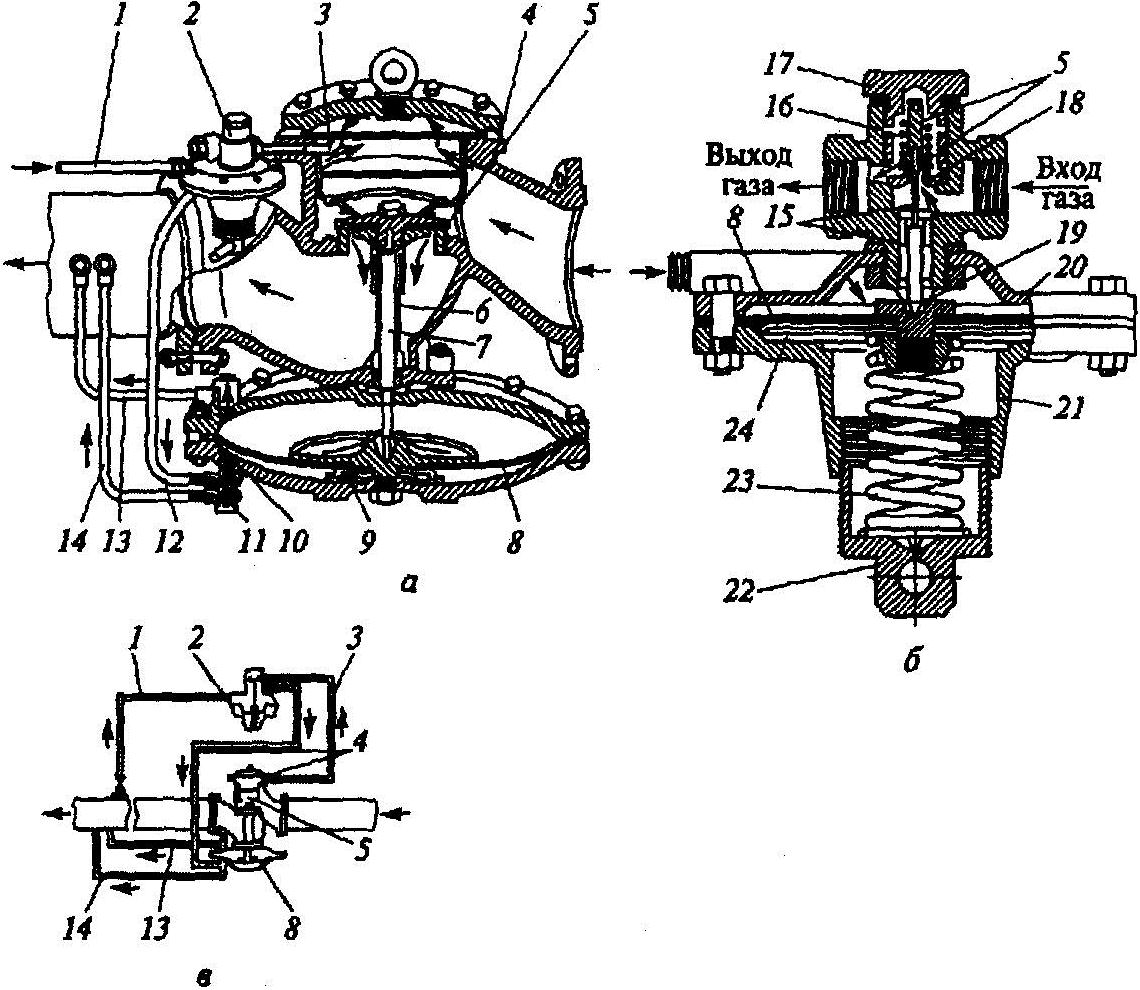
Gas pressure regulator RDG-80(picture below). Combined regulators of the RDG series for regional hydraulic fracturing are produced for conditional passages of 50, 80, 100, 150 mm; they lack a number of shortcomings inherent in other regulators.
Regulator RDG-80
1 - pressure regulator; 2 - pressure stabilizer; 3 - inlet tap; 4 - shut-off valve; 5 - working large valve; 6 - spring; 7 - working small valve; 8 - pressure gauge; 9 - impulse gas pipeline; 10 - rotary axis of the shut-off valve; 11 - rotary lever; 12 - shut-off valve control mechanism; 13 - adjustable throttle; 14 - noise suppressor
Each type of regulator is designed to reduce high or medium gas pressure to medium or low, to automatically maintain the outlet pressure at a given level regardless of changes in flow rate and inlet pressure, as well as to automatically shut off the gas supply in case of an emergency increase or decrease in outlet pressure above the specified allowable values.
The scope of RDG regulators is hydraulic fracturing and GRU reduction units of industrial, municipal and household facilities. Regulators of this type - indirect action. The regulator includes: actuator, stabilizer, control regulator (pilot).
Regulator RDG-80 provides stable and accurate regulation of gas pressure from minimum to maximum. This is achieved by the fact that the control valve of the actuator is made in the form of two spring-loaded valves different diameters, ensuring the stability of regulation over the entire range of flow rates, and in the control regulator (pilot) the operating valve is located on a two-arm lever, the opposite end of which is spring-loaded; the setting force on the lever is applied between the lever support and the spring. This ensures the tightness of the working valve and the accuracy of regulation in proportion to the ratio of the lever arms.
The actuator consists of a body, inside which a large seat is installed. The membrane drive includes a membrane of a rod rigidly connected to it, at the end of which a small valve is fixed; a large valve is freely located between the protrusion of the stem and the small valve, and the seat of the small valve is also fixed on the stem. Both valves are spring loaded. The rod moves in the bushings of the guide column of the body. Under the saddle there is a silencer, made in the form of a branch pipe with slotted holes.
The stabilizer is designed to maintain a constant pressure at the inlet to the control regulator, that is, to exclude the influence of inlet pressure fluctuations on the operation of the regulator as a whole.
The stabilizer is made in the form of a direct-acting regulator and includes a body, a spring-loaded membrane assembly, a working valve, which is located on a two-arm lever, the opposite end of which is spring-loaded. With this design, the tightness of the control regulator valve and the stabilization of the outlet pressure are achieved.
The control regulator (pilot) changes the control pressure in the supra-membrane cavity of the actuating device in order to rearrange the control valves of the actuating device in case of mismatch of the control system.
The over-valve cavity of the impulse tube control regulator is connected through the throttle devices with the sub-membrane cavity of the actuator and with the discharge gas pipeline.
The submembrane cavity is connected by an impulse tube with the supramembrane cavity of the actuator. The control regulator diaphragm spring adjustment screw adjusts the control valve to the desired outlet pressure.
Adjustable throttles from the submembrane cavity of the actuator and on the discharge impulse tube are used to adjust the regulator for quiet operation. The adjustable throttle includes a body, a needle with a slot and a plug. The pressure gauge is used to control pressure after the stabilizer.
The control mechanism consists of a detachable body, a membrane, a rod of large and small springs that equalize the effect of the output pressure pulse on the membrane.
The shut-off valve control mechanism ensures continuous control of the outlet pressure and output of a signal for actuation of the shut-off valve in the actuator in case of emergency increase and decrease in the outlet pressure above the specified allowable values.
The bypass valve is designed to balance the pressure in the chambers of the inlet pipe before and after the shut-off valve when it is put into operation.
The regulator works as follows. To start the regulator into operation, it is necessary to open the bypass valve, the inlet gas pressure enters through the impulse tube into the over-valve space of the actuator. The gas pressure before and after the shut-off valve equalizes. Turning the lever opens the shut-off valve. The gas pressure through the shut-off valve seat enters the supra-valve space of the actuator and through the impulse gas pipeline - into the sub-valve space of the stabilizer. Under the action of a spring and gas pressure, the valves of the actuator are closed.
The stabilizer spring is set to the specified outlet gas pressure. The inlet gas pressure is reduced to a predetermined value, enters the supra-valve space of the stabilizer, into the under-membrane space of the stabilizer and through the impulse tube - into the sub-valve space of the pressure regulator (pilot). The compressive adjusting spring of the pilot acts on the membrane, the membrane goes down, through the plate it acts on the rod, which moves the rocker. The pilot valve opens. From the control regulator (pilot), gas through an adjustable throttle enters the submembrane cavity of the actuator. Through the throttle, the submembrane cavity of the actuator is connected to the cavity of the gas pipeline behind the regulator. The gas pressure in the submembrane cavity of the actuating device is greater than in the supramembrane one. The membrane with a rod rigidly connected to it, at the end of which a small valve is fixed, will begin to move and open the passage of gas through the gap formed between the control of the small valve and the small seat, which is directly installed in the large valve. In this case, the large valve is pressed against the large seat under the action of the spring and the inlet pressure, and therefore the gas flow is determined by the flow area of the small valve.
The outlet gas pressure through impulse lines (without chokes) enters the under-membrane space of the pressure regulator (pilot), into the over-membrane space of the actuator and onto the membrane of the shut-off valve control mechanism.
With an increase in gas flow under the action of a control pressure drop in the cavities of the actuator, the membrane will begin to move further and the stem with its protrusion will begin to open the large valve and increase the gas passage through the additionally formed gap between the seal of the large valve and the large seat.
With a decrease in gas flow, a large valve under the action of a spring and moving in the opposite direction under the influence of a modified control pressure drop in the cavities of the actuating device of the rod with protrusions will reduce the flow area of the large valve and block the large seat; while the small valve remains open and the regulator will start to work in the mode of small loads. With a further decrease in gas flow, the small valve, under the action of a spring and a control pressure drop in the cavities of the actuator, together with the membrane, will move further in the opposite direction and reduce the passage of gas, and in the absence of gas flow, the small valve will close the seat.
In the event of an emergency increase or decrease in the outlet pressure, the membrane of the control mechanism moves to the left or right, the stem of the shut-off valve comes out of contact with the stem of the control mechanism, and the valve closes the gas inlet to the regulator under the action of a spring.
Gas pressure regulator designed by Kazantsev (RDUK). The domestic industry produces these regulators with nominal bores of 50, 100 and 200 mm. Characteristics of RDUK are shown in the table below.
Characteristics of RDUK regulators
|
Throughput at a pressure drop of 10 OOO Pa and a density of 1 kg / m, m 3 / h |
Diameter, mm |
Pressure, MPa |
||
|
conditional |
maximum input |
final |
||
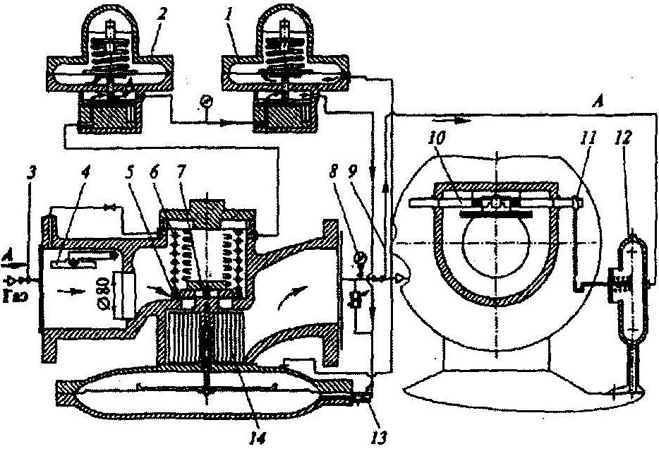
Regulator RDUK-2
a - the regulator in the context; b - regulator pilot; c - regulator piping scheme; 1, 3, 12, 13, 14 - impulse tubes; 2 - control regulator (pilot); 3 - body; 5 - valve; 6 - column; 7 - valve stem; 8 - membrane; 9 - support; 10 - throttle; 11 - fitting; 15 - fitting with a pusher; 16, 23 - springs; 17 - cork; 18 - pilot valve seat; 19 - nut; 20 - housing cover; 21 - pilot's body; 22 - threaded glass; 24 - disc
The RDUK-2 regulator (see figure above) consists of the following elements: a control valve with a membrane drive (actuator); control regulator (pilot); chokes and connecting pipes. The initial pressure gas passes through a filter before entering the control regulator, which improves the working conditions of the pilot.
The pressure regulator membrane is clamped between the body and the cover of the membrane box, and in the center between the flat and cup-shaped disc. The bowl-shaped disc rests against the groove of the lid, which ensures that the membrane is centered before it is clamped.
A pusher rests in the middle of the membrane plate seat, and a rod presses on it, which moves freely in the column . The valve spool is freely hung on the upper end of the stem. Tight closure of the valve seat is ensured by the mass of the spool and the gas pressure on it.
The gas leaving the pilot enters through the impulse tube under the regulator membrane and is partially discharged through the tube into the outlet gas pipeline. To limit this discharge, a throttle with a diameter of 2 mm is installed at the junction of the tube with the gas pipeline, due to which the required gas pressure under the regulator membrane is obtained with a slight gas flow through the pilot. The impulse tube connects the supra-membrane cavity of the regulator with the outlet gas pipeline. The supra-membrane cavity of the pilot, separated from its outlet fitting, also communicates with the outlet gas pipeline through the impulse tube. If the gas pressure on both sides of the regulator diaphragm is equal, then the regulator valve is closed. The valve can only be opened if the gas pressure below the diaphragm is sufficient to overcome the gas pressure on the valve from above and overcome the gravity of the diaphragm suspension.
The regulator works as follows. Initial pressure gas from the over-valve chamber of the regulator enters the pilot. After passing the pilot valve, the gas moves through the impulse tube, passes through the throttle and enters the gas pipeline after the control valve.
The pilot valve, throttle and impulse tubes are throttle-type amplifying devices.
The final pressure impulse perceived by the pilot is amplified by the throttle device, transformed into command pressure and transmitted through the tube to the submembrane space of the actuator, moving the control valve.
With a decrease in gas flow, the pressure after the regulator begins to increase. This is transmitted through the impulse tube to the pilot diaphragm, which moves down to close the pilot valve. In this case, the gas from the high side of the impulse tube cannot pass through the pilot. Therefore, its pressure under the regulator membrane gradually decreases. When the pressure under the membrane is less than the gravity of the plate and the pressure exerted by the regulator valve, as well as the gas pressure on the valve from above, the membrane will go down, displacing gas from under the membrane cavity through the impulse tube to the vent. The valve gradually begins to close, reducing the opening for the passage of gas. The pressure after the regulator will drop to the set value.
With an increase in gas flow, the pressure after the regulator decreases. The pressure is transmitted through the impulse tube to the diaphragm of the pilot. The pilot diaphragm moves up under the action of the spring, opening the pilot valve. The gas from the high side flows through the impulse tube to the pilot valve and then through the impulse tube goes under the regulator diaphragm. Part of the gas goes to the discharge through the impulse tube, and part - under the membrane. The gas pressure under the regulator membrane increases and, overcoming the mass of the membrane suspension and the gas pressure on the valve, moves the membrane upward. The regulator valve then opens, enlarging the opening for the passage of gas. The gas pressure after the regulator rises to a predetermined value.
When the gas pressure increases in front of the regulator, it reacts in the same way as in the first case considered. When the gas pressure drops in front of the regulator, it works in the same way as in the second case.
Product composition
The gas pressure regulator RDG-N includes: an actuator 2, a filter 13, a pressure gauge 17, a stabilizer 16, a control regulator (KN-2) 15, a control mechanism 12, a throttle 8, 8a, in accordance with Figure 1; RDG-V actuator2, control regulator (KV-2) 15, control mechanism 12, filter 13, throttle 8, 8a in accordance with Figure 2.
Completeness
Table 2.
Notes: The manufacturer supplies the regulator RDG-N and RDG-V with the setting for the minimum outlet pressure according to paragraph 3 of Table 1.
Device and principle of operation
The gas pressure regulator is manufactured in two versions RDG-N in accordance with Figure 1 and RDG-V in accordance with Figure 2.
Actuator 2 automatically maintains the specified outlet pressure in all gas flow rates by changing the gap between valve 4 and seat 3.
The actuator 2 consists of a body with a seat and a guide column 3, a membrane with a rigid center 6, clamped around the perimeter between the top and bottom covers and connected in the center by a pusher with a rod 5, freely moving in the bushings of the guide column and pushing the valve 4.
Filter 13 is designed to clean the gas used to control the regulator from mechanical impurities entering the regulator from the hydraulic fracturing or GRU system.
The filter 13 consists of two housings, one of which has a fitting for the pressure inlet, the second has an outlet for the pressure outlet.
A filter element is placed between the housings.
The pressure gauge is designed to control the outlet pressure after the stabilizer or to control the inlet pressure to the control regulator (KN-2).
The stabilizer 16 is designed to maintain a constant pressure at the inlet to the control regulator, i.e. to exclude the influence of inlet pressure fluctuations on the operation of the regulator as a whole and is installed only on the low pressure regulator RDG-N in accordance with Figure 1. The pressure on the pressure gauge after the stabilizer should be 0.2 MPa (to ensure the required speed).
The stabilizer 16 is made in the form of a direct-acting regulator and consists of a valve with a seat and a seat overlap bar with a load spring and a membrane assembly with a rigid center, pinched along the perimeter by two housings and connected in the center by a pusher to the valve bar.
Control regulators KN-2 and KV-2 generate control pressure for the submembrane cavity of the actuator in order to rearrange the control valve.
The control regulator KN-2 in accordance with Figure 1 and KV-2 in accordance with Figure 2 consists of a regulator head with two fittings for inlet and outlet pressure, a membrane chamber with a fitting for supplying an input pressure pulse. The membrane assembly with a rigid center and a spring load is clamped along the perimeter between the body and the cover and is connected in the center by a pusher to the head valve.
The KN-2 Low Pressure Control Regulator uses replaceable load springs to provide a full range of outlet pressure. Spring KPZ-50-05-06-02TB (?2.5) provides Pout=0.0015...0.0030 MPa, spring RDG-80-05-29-06 (?4.5) provides Pout=0 .0030...0.0600 MPa.
The high pressure control regulator KV-2 is equipped with a stronger spring, a support washer and a cover with a smaller working area.
Adjustable chokes 8 and 8a in the submembrane cavity of the actuator and on the impulse tube serve to tune the regulator to a quiet (without self-oscillations) operation.
Adjustable throttles 8 and 8a each consist of a throttle 18 and a fitting 19 in accordance with Figure 3.
The shut-off valve control mechanism 12 is intended for continuous monitoring of the outlet pressure and issuing a signal for actuation of the shut-off valve in the actuator in case of emergency increase and decrease in the outlet pressure in excess of the allowable preset values.
The control mechanism 12 consists of two detachable covers, a membrane unit clamped along the perimeter by covers, a rod of the control mechanism 11, a large 22 and a small 21 spring, balancing the action of the outlet pressure pulse on the membrane.
The regulator works like this:
Gas under inlet pressure enters through filter 13 to stabilizer 16, then under pressure of 0.2 MPa to control regulator (KN-*) 15 (for RDG-N version).
From the control regulator (for the version RDG-N), the gas flows through the adjustable throttle 8 into the submembrane cavity of the actuator.
The supra-membrane cavity of the actuator through the throttle 8a and the impulse tube 9 is connected to the gas pipeline behind the regulator.
The pressure in the submembrane cavity of the actuator during operation will always be greater than the outlet pressure. The supra-membrane cavity of the actuating device is under the influence of the outlet pressure. The control regulator (KN-2) (for the RDG-V version) maintains a constant pressure, so the pressure in the submembrane cavity will also be constant (in steady state).
Any deviations of the outlet pressure from the set one cause pressure changes in the supra-membrane cavity of the actuator, which leads to the valve 4 moving to a new equilibrium state corresponding to the new values of the inlet pressure and flow rate, while the outlet pressure is restored.
In the absence of gas flow, valve 4 is closed, because there is no control pressure drop in the supra-membrane and sub-membrane cavities of the actuator and the action of the outlet pressure.
In the presence of a minimum gas consumption, a control pressure drop is formed in the supra-membrane and sub-membrane cavities of the actuator, as a result of which the membrane 6 with the rod 5 connected to it, at the end of which the valve 4 is fixed, will move and open the gas passage through the resulting gap between the valve seal and saddle.
With a further increase in gas flow under the action of a control pressure drop in the above cavities of the actuator, the membrane will move further and the rod 5 with valve 4 will begin to increase the passage of gas through the increasing gap between the valve seal 4 and the seat.
When the flow through the valve 4 decreases under the influence of a changed control pressure drop in the cavities of the actuator, it will reduce the passage of gas through the decreasing gap between the valve seal and the seat and subsequently close the seat.
In the event of an emergency increase or decrease in the outlet pressure, the membrane of the control mechanism 12 moves to the left or right, the shut-off valve lever comes out of contact with the stem 11 of the control mechanism 12, the shut-off valve, under the action of the spring 10, closes the gas flow to the regulator.
In connection with the constant work to improve the regulator, changes may be made to the design that are not reflected in this OM.
Marking and sealing
The regulator is marked with:
- Trademark or name of the manufacturer;
- Regulator designation;
- Product number according to the manufacturer's system;
- Year of manufacture;
- Conditional pass;
- Conditional pressure;
- Conditional throughput;
- Sign of the direction of the flow of the medium;
- Code of technical conditions;
- Mark of conformity for mandatory certification.
Marking is applied on the plate in accordance with GOST 12969-67 and the regulator body, except for the nominal capacity, which is given in the OM.
Shipping container marking complies with GOST 14192-96 1.7 with warning signs according to drawing RDG-80 TrVSb.
The container is sealed with a bandage tape M-0.4 ... 0.5x20 along the perimeter of the container GOST 3560-73.
Package
The regulator is installed in a wooden box and securely fixed in it. Operational documentation and a set of spare parts are wrapped in waterproof paper, packed in a plastic bag and placed in a box with a regulator.
Picture 1 (Gas pressure regulator RDG-N)
Figure 2 (Gas pressure regulator RDG-V)
1-shutter valve; 2-executive device; 3-saddle; 4-valve working; 5-rod; 6-membrane of the actuator; 7-throttle washer; 8 throttles adjustable; 9-tube impulse input gas pipeline; 10-shut-off valve spring; 11-rod control mechanism; 12-control mechanism; 13-filter; 14-candle; 15-control regulator (KN-2); 16 stabilizer; 17-manometer; 18-lever pressure shut-off valve; 19-bracket; 20-screw; 21-spring small; 22-spring is large; 23-staples; 24-bracket; 25-reg. small spring screw; 26-reg. large spring screw; 27-bracket.
Figure 3
18-throttle; 19 fitting.
Intended use
1. Operating restrictions.
1.1. Controlled environment - natural gas in accordance with GOST 5542-87
1.2. The maximum allowable inlet pressure is 1.2 MPa.
2. Preparation of the product for use.
2.1. Unpack the regulator.
2.2. Check the completeness of the delivery in accordance with paragraph 1.4.1. RE.
2.3. Check the regulator by visual inspection for the absence of mechanical damage and the integrity of the seals.
2.4. Instructions for product orientation.
2.4.1. Regulators are installed on a horizontal section of the gas pipeline with the membrane chamber down. Accession of regulators to a gas pipeline flange in accordance with GOST 12820-80.
2.4.2. The distance from the bottom cover of the membrane chamber to the floor and the gap between the membrane chamber and the wall when installing the regulator in the hydraulic fracturing and gas distribution unit must be at least 100 mm.
2.4.3. A technical overpressure gauge MGP-M-1.6MPa - 2.5 TU 25 7310 0045-87 is installed in front of the regulator to measure the inlet pressure.
2.4.4. A two-pipe pressure and vacuum gauge MV-1-600 (612.9) TU 92-891.026-91 is installed on the outlet gas pipeline near the outlet of the impulse tube when working at low pressures or an overpressure gauge MGP-M-0.1 MPa - 2.5 TU 25 7310 0045-87 when operating at medium gas pressure to measure the outlet pressure.
2.4.5. The impulse pipeline connecting the regulator with the sampling point must have a diameter of Du for RDG-50 and RDG-80 and Du35 for RDG-150 in accordance with Figure 5. The connection point of the impulse pipeline must be located on top of the gas pipeline at a distance of at least five nominal diameters from output flange of the product.
2.4.6. Local narrowing of the passage section of the impulse pipe is not allowed.
2.4.7. the tightness of the actuator, stabilizer, control regulator, control mechanism is checked during a trial run of the regulator. In this case, the maximum inlet and one and a half times the outlet pressure for this regulator is set, and the tightness is checked using a soap emulsion. Pressurization of the regulator with pressure, the value of which is higher than that indicated in the passport, is unacceptable.
2.4.8. During commissioning, it is not allowed:
- Shutting off the impulse pipeline connecting the outlet pressure measurement point with the regulator column.
- Release of input pressure in the presence of output and control differential pressure on the working membrane of the actuator of the regulator.
2.4.9. To increase the speed of the regulator when operating at input pressures of not more than 0.2 MPa, it is allowed to remove the stabilizer (in RDG-N) and supply input pressure to the control regulator directly from the filter (according to the RDG-V scheme) in accordance with Figure 2.