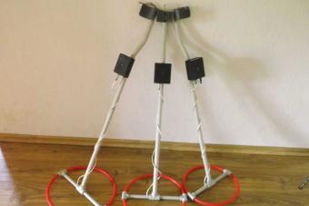
Manufacture homemade This kind requires special skills and knowledge. If this is your first self-timer, such a type, you should seek help from a specialist (for your own security).
The article only demonstrates the process of manufacturing the power supply. The author of the article is not responsible for any damage or injury caused by the use of this information.
Step 1: Introduction
This power supply was designed to supply a constant voltage of about 50 square meters. It can easily be converted to an adjustable BP by connecting the rheostat (in the case of using a transformer) or add additional power control circuits.
The total cost of about 15 €, as most parts (transformer, bridge rectifier, radiator, switches, cables ...) were taken from old technology, the only parts that were purchased are timer 555, connectors and capacitors.
Step 2: Materials
- Transformer + rectifier bridge + capacitors;
- Switches and connectors;
- Shrink tubes;
- Male and circuit board;
- 555 timer;
- 8 pin nest;
- 7812 (if the incoming power is 555\u003e than 14,5 or lower than 35V);
- Small radiator for 7812 (if necessary);
- 2 * 100 NF;
- 1 * 1 μF;
- 1 * 10nf;
- 1 * 68 μF (or 100 μF);
- 2 * 4148 diode;
- 3 * 10K;
- (1 mop) 10R;
- 1 * 680R;
- 1 * 470r;
- 1 * 10K variable resistor;
- 1 * 100K variable resistor;
- 2 * Handles for variable resistors;
- 1 * 2N2222 and 2N2907 (or other NPN-PNP steam);
- 1 * infrared sensor;
- 1 * Infrared LED;
- 1 * BC547 (or similar: 2n2222I 2N3904);
- 2 * insulating high voltage connector;
- 3 * IRF540N MOS, but recommend 1 * IRFP260;
- Radiator for transistors (and fan, if necessary);
- Buttons;
- Transformer for lowercase sweep from the old television or computer monitor;
- Thick copper cable (about 1 meter);
- Epoxy adhesive.
Step 3: Calculations

The only calculation that needs to be executed is the calculation of the capacitors value (if you are using a transformer).
In my case, I used 20,000 UF. You may need to add 10000UF or 20000UF to see the effect at the output. Pulsation created due to changes in currents can change the correct operation of the control, as a result, the efficiency will decrease and the arc will decrease.
Step 4: Making a box


Each power supply needs a reliable box that will hide the chain components. Obvious materials for the hull are wood and plastic.


I chose a tree, because it will further exempt the elements of high voltage.

Note: If you plan to paint the case, first check the paint for conductivity at large stresses.

ATTENTION: Despite the fact that the wood is a very good insulator, it can accumulate moisture. I recommend to dry wood in the oven before making the body, then apply a uniform paint layer.

Step 5: Control Scheme

We collect a small scheme based on the 555 timer with an adjustable frequency and a working cycle (from 5-50KHz and 5-50% of the working cycle), it has its own 12B input, which does not depend on the transformer.


Three IRF540N connect in parallel (you can use one IRFP260N). With this configuration, they barely heated, even with full load.


Add a button to the chain with a 1K resistor (an IR sensor should be placed in this place). You can modify the scheme and remove the transistor, leaving the button and connected to 4 conclusion 10k resistor running to the ground.

Note: In order to translate a duty cycle from 5 to 50% (and not from ~ 5% to 100%), place 10K resistor, as shown in the figure. This resistor should be placed in an assembly with a diode in front of the condenser. If you connect it to a row with another diode, then in the final total you will adjust the working cycle from 50 to 100%.


Step 6: We deploy wiring
After making sure that the scheme works properly connect MOS - transistors in parallel (to make it connect all the "Strokes" and "sources" of cables "for a high current" by adding 10 ohms for each conclusion and connect them together.


Bill the power cable connector and switch to the box, connect them (it is very important to use heat shrink tubes to protect the connections).

ATTENTION: Button is preferable to the switch! In the event of an accident, the button will sink back and tear the chain. Never use a switch as a chain burst.

After the control circuit has been collected, you can proceed to connecting BP.

Step 7: Installation of the Power Supply

After finding a suitable power source, I will attach it to the scheme. Connect the 12V power supply together with the transformer to one switch output, as shown in the picture. Connect the transformer to the bridge rectifier, and then condensers using a heat shrink tube for insulation of the circuit connections.

Connect the power to the "reverse move" and MOS transistors, as shown in the next step.

Step 8: Preparation, Connection and Reverse Insulation


We will probably be about 10 turns of thick wire around the core of the primary winding. The positive output of the power supply is connected to one of the ends of this wire, and the other end is connected to the "stock" of the field transistor. For connections can use terminal blocks. We solder wires and cover all contacts with epoxy resin.
The need for a laboratory power supply with the ability to adjust the output voltage and the threshold for the protection of the current consumption current has long arose.
Having worked on a bunch of material on the Internet and stabbing a bump on own experienceI stopped on this development.
This power supply is good for repetition, but its output voltage depend on the supply voltage of the operating amplifier TL081, and if it was + 31V, then at the output of this BP, the maximum voltage was no longer.
The estimated output voltage of the secondary winding of the power transformer of this BP was 24V, standing at the input of the stabilizer (after the bridge) + 31B. With an increase in the exit load to the calculated (for me - 5a), the output voltage of BP fell, and as a result, the power of the OU, accordingly walked, i.e. It was traced as an option - not the stability of the output voltage at the boundary currents (it didn't really happen when he drove the amp on the TDA7293, and at MAX the power did not go to the spread ...).
To eliminate this disadvantage, in the described design of your BP, I increased the voltage at the input of the stabilizer to + 45V and, accordingly, so that the OU did not fail, (the boundary power supply in TL081 - 36 volts), put a parametric stabilizer on the OU power circuit.
The voltage control range in its power supply unit left 0-30 volts, the current to the load is determined mainly applied by the transformer, in my version I calmly remove more than 5 amps from it. For each power supply channel on the transformer there is its own winding.

There is an adjustment of the shift threshold for the current flow consumed, as well as a short-circuit protection in the load. The display is made on the LCD LSD8X2, LSD16X1 or LSD16x2 display.
By the way about the indication;
In the aforementioned power supply, the current and voltage indication was also performed on the LCD display, but on one indicator, and the author had to be wise with the connection of such an indicator to a two-polar power supply.
I went to another way and put my own current and voltage indicator on each channel. As a result, he received two fully independent power supply (channel), which can be turned on and parallel and sequentially (two-polar or doubled), where the load current of each channel to 5a.

To simplify the winding of the power transformer, I added a stabilizer to power a voltammermeter in the BP scheme, and now each channel of the BP stabilizer and a voltammermeter is powered by one winding.
The scheme and the description of the voltammermeter to bring here (duplicate) I see no point, I took them from here, and you can also see and
And so I bring the scheme of the power unit of one channel, the second is absolutely identical.

The entire diagram of a single power supply channel is collected on the printed circuit board. 125x65 mm.


Output transistors and diode bridges are installed separately, for each channel on its radiator.

Initially, three pieces of CT819G in the plastic case (TO220) and a 10 ampere diode bridge on the channel used as the output transistors.
The diode bridge was installed on the power supply board and had its own separate radiator.

Then in the process of operation of the power supply in heavy conditions, the output transistors could not withstand bullying and "flew" from overheating. Also, the diode bridge at 10 amps did not behave very well.
Therefore, as the weekend transistors, the power TIP35C (two pieces in the parallel, the COPLE-247) also put the TIP142 (analogue - KT827), and behave normally.

Well, accordingly, the diode bridge changed (at 24 A) and put it as well on the overall radiator.
When testing, I have a maximum load current was 8 amp, and the weekend transistors were warm as irons. In this regard, it was necessary to limit the maximum current of the load up to 5 amps, put fans to each radiator, also put the thermal protection from overheating.

After the year of operation, improved in this way, the power supply, and as a laboratory BP, and as a charger, and with parallel and consistent operation of its channels, there are no complaints to it.

The entire diagram of the power supply, as I said above, is collected on a printed circuit board, 125x65 mm.
Circuit compounds of fees with regulators, power transformer, output transistors, etc. connections, shown in the figure below.
The overall layout of all blocks inside the case.


The power transformer was used in the power supply with a calculated power of about 350 W. The primary winding is wound with a wire, a diameter of 0.7-0.8 mm, and two secondary windings - with a wire of 1.2-1.5 mm. with output voltage 32-33 volts.
The transformer motor data does not cite, as it has been moving for a long time, and they are not enough for. In practice, every radio amateler puts himself such a trance, which will find, or it will be able to get it, if only the power of the trance was not less necessary.
Now a brief explanation of a piece of schemes made changes and additions of the original.

On the transistors VT1, VT2, and the DA1 operational amplifier, the overheating scheme is collected.
Thermistor R2 is overheating sensor. It is installed on the radiator of the output transistors. LED - overheating indicator.
Operational output, through the buffer transistor VT3 controls the relay K1, which contact K1.1 when overheating, closes the average output of the voltage adjustment resistor to the shared wire, thereby reducing the output voltage of the power supply to zero.
On the Transistor VT4, a 12 volt stabilizer is assembled for powering a voltammermeter of its channel.
The following thermal protection scheme is designed to be powered by a five-wing source. It uses a fan to operating voltage 5 volt.
It was added by our user site Yuri ( Yura_rus.). Maybe someone comes in handy if there are 5 volt fans.

Below in the attachment (in the archive) all the necessary files and materials for the assembly of this power supply are collected.
If someone has any questions and misunderstandings on the assembly and commissioning of this BP, then ask them in a similar topic. If possible, I will try to answer and help to deal with all the difficulties that have arisen in the process of assembling this BP.
Good luck to all and all the best!
Archive "Two-channel powerful laboratory power supply". "
If you connect to a socket directly, it will occur its instant combustion, it will become black, let it smoke and, accordingly, the shining will not be shining. Therefore, you should not do so.
Such tapes are powered by voltage in or. The tapes are 12 in the cost less, and it is easier to acquire them.
To transform the voltage of the network 220 volts at 12, 24 and 36 volts apply pulse block Power (BP). The key parameter in its power, which it can give the LED tape.
Calculation of Power BP is advisable to consider on the example.
There are two 5-meter, 30 LEDs / M, which should be powered.
First of all, it is worth determining which power is consumed 1 m of this tape.
Power 1 m tape - 7.2 W. Total is 10 m (2 reels of 5 m). Accordingly, the power consumed is 72 W (10x7.2). To avoid rapid combustion from the overload of BP, it must have a minimally 30 percent reserve for power. As a result, it turns out 93.6 W (72x130% / 100%).
Accordingly, for the washed of 10 m tape LED with thirty LEDs per 1 m need a PP of the specified power.
There is a minimum of 3 versions of BP available for purchase in stores selling LED tapes.
BP for LED Tape (options)
(1) Sealed compact BP having a plastic case
Small dimensions, waterproof, lightweight. But its power does not exceed 75 W. Therefore, for the washing of two tapes will be needed 2 BP software. It is used in the backlight of the interiors, because it can be quite easily hidden.
(2) Hermetic BP having an aluminum case
It has power. Its one is enough to pick up two tapes at once. But his mass is over 1 kg, besides large dimensions. Mainly applies to illuminate signage on the street because it possesses high degree reliability and good protection from external influence (rain, frost, sun).
(3) Outdoor BP
It has a power of 100 W, but in size more than the above. As a rule, it is not used to illuminate walls or ceilings. It is impossible to hide it in a niche. It is used to power the equipment, they are installed, as a rule, in specialcaps or hardware compartments. It has a relatively low price.
Thus, for the selection of BP, first of all, you should look at the tape type that is planned to be powered. Then see the power consumed 1 m of this tape. After that, determine the power of BP, moving this value with the length of the tape and add a stock in the amount of 30%. As a result, choose the most suitable BP of those options that are on sale.