 And in translation it is simply "do not dig." After all, how often do we laugh at communal workers about the fact that the road services did not have time to lay asphalt, when it was blown up for laying a heating main. Another situation: on the one hand, a highway of republican or international importance began to become swamped and flooded, it was necessary to lay a pipe under it to drain water, but it was impossible to dig the road - there was no detour. Or: through an old park, where every tree is a monument of history and nature, it is necessary to lead gas and water to the manor, which has become a museum ... Thanks to new technologies, in particular, trenchless laying of communications, all these tasks are solved quickly and painlessly for nature.
Ways of trenchless laying of communications
There are at least seven of them, but the choice of a specific method depends on the purpose and depth of the laid communications, on their size, on the mechanical composition of the soil, on the length of the hole being made, on the power of the power drive.
The most common are the following:
- - method of horizontal mechanical drilling;
- - method of puncture and punching;
- - method of shield penetration.
All of them ensure the integrity and normal functioning of above-ground and underground facilities, reduce the time for laying communications, and reduce their cost.
Horizontal mechanical drilling
 Although this is one of the first ways trenchless laying communications, however, it is very often used now. Often this operation is abbreviated as HDD (horizontal directional drilling), since this drilling is quite controllable in the thickness of the earth.
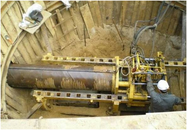
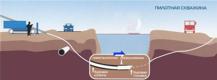
The process of horizontal drilling can be divided into several stages. The first one is drilling a pilot well. This is a very responsible operation, the location of the pipeline underground and the place of its exit depend on it. This is done in the following way. A rock cutting tool is a drill head with a built-in emitter for location. Also in the drilling head there are holes for the exit of the drilling fluid supplied through the hollow rods. Thanks to the locator located at the operator, signals about its location, azimuth and slope are recorded from the drill head. Having on the display a diagram of other communications and objects and the trajectory of the movement of the head, the operator manipulates its movement: first "stop", then measuring and changing the angle of the direction of movement, then again continuing the movement, but in a given direction. The direction of movement of the head is changed due to the oblique cut on the head: the cut indicates the direction in which the head will go at the beginning of the movement after the drilling fluid is applied.
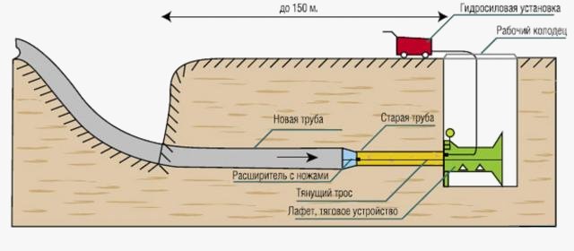
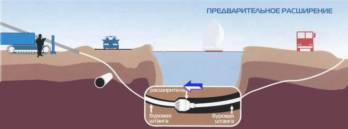
After the head has exited at the point defined by the project, the next stage begins. The drill head is disconnected from the rods, and an expander (rimmer) is connected, which, together with the rods, goes in the opposite direction. The rimmer has a diameter one and a half to two times larger than the diameter of the pipe. Rotating, it easily expands the pilot well to the desired size.
A cap with a swivel is attached to the retractable end of the pipeline. The pipeline is retracted behind the rimmer, while the swivel is needed so that the pipe does not rotate according to the translational-rotational movement of the rimmer. Thanks to all these sequential operations, the pipeline lies exactly along the design trajectory.
Horizontal puncture
 Most often, punctures are performed under roads and railways. At first, two pits are dug: starting and receiving. A frame with jacks is placed in the starting pit. The pipe being laid is equipped with a tip, which makes it easier for it to pass through the ground. A pipe with a tip pierces the ground under the action of jacks. As soon as the open part of the pipe approaches the point of entry into the ground, the next section is attached to the pipe. The well around the pipe is compacted soil. Puncture speed and energy consumption depend on soil porosity, pipe material (different friction), well size and puncture method. The types of puncture include hydro-puncture (a powerful jet of water is fed into the pipe) and vibro-puncture (using vibratory hammers). Sometimes a puncture is made using a special mechanism - a pneumatic punch, inside the body of which there is a drummer driven by compressed air. Due to impacts, the front end of the mechanism moves forward, while the reverse motion is prevented by the friction of the mechanism body against the ground. Low friction in swampy areas does not allow the use of a pneumatic punch there. He will not take rocks either, as he goes astray even in soft ground if he runs into a stone. A puncture usually pulls pipes with a diameter of up to 426 mm for a length of 25-50 meters.
Punching method
 It is in many ways similar to the horizontal puncture method. Ditches are also dug, and a frame and jacks are also installed. But then the main difference begins: the pipe is not supplied, as with a puncture, with a tip, it is supplied with an open end. The pipe is equipped with a knife along the front edge, it is pressed into the ground by jacks operating cyclically, that is, in forward and reverse motion. When pierced, the soil moves apart, is pressed and compacted around the pipe, when punched, the soil enters the pipe with a cork. The soil from the pipe is removed manually or by mechanisms.
To facilitate the work, hydraulic jet and vibro-impact installations can be used. The combination of a hydraulic monitor for soil erosion and an auger installation that removes soil to the surface of the earth greatly facilitates and speeds up the process of punching. This method allows you to lay pipes with a diameter up to 2-3 meters about 60 meters . A shift usually takes about 10 meters.
Shield penetration method
 It is used in urban conditions for tunnels and cylindrical galleries, for driving underground lines. They lay communication lines with a diameter of 2 to 10 meters.
First, an assembly shaft is prepared, along which the shield is lowered into the face. Then, work is carried out that will ensure the normal functioning of the tunneling in the future: ventilation is arranged, electricity is supplied, soil drainage systems are laid, and a tunneling shield is mounted.
It is a steel shell, under the cover of which excavation and removal of soil is carried out. Consists of the following parts:
- - anterior wedge-shaped;
- - reference average;
- - rear tail.
In the front wedge-shaped part, loosening, collection and removal of soil are carried out. Jacks are located in the middle part, which advance the shield during penetration. In the rear part, work is being done on the lining of the walls of the passed tunnel.
Benefits of trenchless technology
The growth of cities and the constant improvement of their infrastructure require constant changes in communication systems. And so that this process does not turn into a constant digging of the streets, trenchless technologies for laying communications are used. They have a number of undoubted advantages:
- - mobility and compactness;
- - reduction of the cost of works due to the reduction of the terms of their implementation;
- - minimal damage, therefore, reducing the cost of restoring surrounding objects;
- - speed of work;
- - multidisciplinary application of technologies (for pipelines, sewer networks, drainage systems, etc.);
- - the possibility of carrying out work in specific conditions: under rivers and lakes, under existing roads and airfields, under floaters, even under the English Channel, that is, under the water column in rocks;
- - environmental friendliness of the process.
Aesthetics and ecology
 Endless ditches and trenches are already not pleasing to the eye, but what if they are also located in frequently visited places or recreation areas? Once in your life you got out to look at St. Basil's Cathedral, and the road there was blocked by excavators and ditches dug by them. Well, how does it feel? How many conflicts arise, how many pickets are put up if a growling bulldozer appears in an old square. Even if earth-moving equipment does not uproot the tree, it will damage the root system. Often, after digging trenches, the groundwater level drops, which only harms the local flora, or even leads to its disappearance. No matter how we separate the fertile layer and the parent rock when digging, when the trench is dug in, the soil will mix, which leads to a change in the biocenosis. In place of the former trenches, bumps and dips appear due to precipitation and temperature changes, because it is impossible to achieve uniform soil compaction when backfilling the trench.
Trenchless laying of communications allows avoiding violation of the integrity of the environment, does not require funds for landscape restoration, while starting and finishing pits are point violations, in addition, manholes are installed in their place to control pipelines.
More about large machinery, equipment and transport :
- Excavators. Complete classification.
Pipeline installation is a rather complicated matter, although at first glance everything is very clear. Especially when we are talking about large trunk works. The point is that it is not always specifications allow digging trenches for laying, but at the same time, not all communications, for technical reasons, are able to go above the ground, for example, on struts.
In a number of such cases, the trenchless method of laying pipes is applicable.
What it is?
Trenchless pipe laying is a set of measures for creating a communication wire, in which the method of digging a trench is replaced by a number of other works, and the preliminary deepening itself is not performed.
This method applicable for the following communications:
As for the materials of the pipes themselves, it does not play a special role for the use of one of the alternative methods. Therefore, trenchless laying can be made of both metal and polymer products, only taking into account the characteristics of the material and its compounds.
Share several of the most popular methods of trenchless work.
Horizontal directional drilling
One of the most common options. In this case, a special drilling rig is used for installation. Its popularity lies in the relative reduction in time and power costs. In particular, this method is perfectly applicable in difficult ground conditions, for example, in the presence of quicksand, lakes, ravines. Or if there are other elements of urban planning: squares, parks, roads, etc. This method is used without opening the surface layer of the earth, which does not spoil the overall landscape. This method is validated and approved.
![]()
Punching of steel cases
So, the method consists in the following manipulations. With the help of special devices, hydraulic jacks, a case made of metal (steel) is pressed into the ground. One end of the pipe is equipped with a knife. This procedure facilitates the process of entering the ground and reduces damage to the surrounding area. After the start of work, the soil enters the pipe due to high pressure and its hollow space. Then he is taken out of the slaughter. In total, three stages of punching can be distinguished.
- Development of a pit, the width of which should not be less than 3.5 meters, and the length - 4 meters. It must be reinforced, have a depth of half a meter below the pipe tray.
- Wall preparation for jacks. In this case, a special solution is poured, forming a wall, which will be the emphasis for the equipment.
- Installation of power equipment is already in the pit. The hydraulic equipment itself can consist of several cylinders (from 1 to 4). The force of the jacks, depending on the soil, ranges from 100 to 500 tons.
Microtunnelling
This sewer construction method is well suited to urban environments where space is limited. For this method, special equipment is used - a tunneling microshield, which translational movements provides a powerful jacking station that transmits the pushing force through the column of reinforced concrete pipes to the shield.
For this, special drilling rigs are used. Drilling takes place without leaving the working pit to the surface to the receiving one. And a special puncher lays pipes of large diameter, more often from 400 to 1200 mm. The drilling process takes place in several stages.
road puncture
This method is applicable to most types of communications. At the same time, it can be used both in the basements of houses and in existing wells.

Features of trenchless pipe laying:
- Reduced turnaround time for even the largest jobs.
- Increase in temporary seasonal gap. Thanks to the installations, pipe installation can be carried out in cold weather.
- Cost reduction.
- Minimal red tape associated with the approval of work and obtaining the necessary documentation.
- Compactness. Possible work even in tiny urban areas.
New technologies are being introduced into modern industries very quickly. Thus, it is possible that the trenchless method of laying communications will soon completely replace the classic one with large-scale digging of trenches and immersing pipes in them.
The most common is the open method of laying pipes in the ground, when a trench of the required depth is dug, a pipeline is installed in it, after which the trench is buried. This method has its drawbacks:
- the fertile soil layer is disturbed;
- green spaces are being destroyed;
- if the trench passes through the road, then the asphalt coating is destroyed, which will then need to be restored, and if the road cannot be blocked, then laying the pipeline in an open way in such a section becomes impossible at all.
To lay a pipeline under a railway, river, residential building, highway, etc. using trenchless methods of laying pipelines. Trenchless drilling technologies make it possible to carry out underground work without opening the ground, which eliminates the need to restore asphalt road surfaces, disrupt existing communications, block roads, destroy trees and landscaping, etc.
The advantages of trenchless technologies include:
- reduction of material costs;
- reduction of working time;
- reduction of the working personnel required for the work;
- minimizing harm environment;
- the possibility of laying communications in the winter;
- the absence of trenches and mechanisms increase the safety of work.
If it is necessary to make a small section of trenchless pipeline laying, such as, for example, a puncture under the road. That can be done with special machines and equipment. It will only be necessary to make a cylinder of the desired diameter with an extendable rod attached to it. And with the help of it, manually select the ground from under the road, having previously dug trenches on both sides. When the puncture is measured in tens of meters or more, then the use of special mechanisms will be required.
There are several ways of trenchless laying of pipelines:
The laying of communications by the horizontal directional drilling method consists of three stages:
1. Laying a pilot well.
This is the most important stage of work, on which the final result will largely depend. Drilling of a pilot well is carried out with a drill head made of replaceable carbide inserts. The drilling head is connected to a flexible rod, which allows it to move along a given trajectory and bypass all sorts of obstacles in its path. Also in the head there is a hole through which the drilling fluid is supplied to cool it, as well as liquefy the crushed rock, for its subsequent withdrawal to the surface. Control over the drilling trajectory is carried out using a navigation unit located in the cavity of the drill head. It transmits the position, slope and azimuth of the drill head to the control panel, which allows you to accurately lay the well, bypassing all sorts of obstacles in its path. With accurate calculation and high qualification of the service personnel, the drill head comes out in the place specified by the project.
2. Well expansion.
After the pilot well is ready, the head is disconnected from the rod and a special expander is installed in its place. The reamer is pulled from the exit point to the drilling machine, thereby expanding the hole to the desired diameter. With large pipeline diameters, well expansion can be carried out in several stages in order to reduce the load on the equipment. It should also be taken into account that the diameter of the well should be 30% larger than the diameter of the pipe.
3. Pulling the pipeline.
The lash of the pipeline is attached to the rod through an expander and a special hinge (earring), after which the HDD machine pulls it into the well. The tightening process also uses drilling fluid to reduce friction and protect the pipe from mechanical damage.
The most common artificial barriers in the laying of external water supply and sewerage networks are automobile and railways. On the main roads, traffic is so intense that even at night it is difficult to choose a period of time for the installation of a trench crossing the road and laying in it. In such cases, apply.
Trenchless pipeline laying is performed in several ways: puncture, punching, horizontal drilling and shield penetration. The choice of each of these methods is influenced by various factors: soil and hydrological conditions; the nature of the structures above the crossing; requirements for pipeline insulation; length and accuracy of penetration; the diameter of the pipelines being laid and the economic justification of the proposed method.
Puncture most often used for laying pipelines in clay and loamy soils with pipe diameters up to 600 mm. The length of the laying in this way reaches 60 m. In this case, the soil is not developed, but compacted in the radial direction around the pipe. Puncture requires very significant forces (from 150 to 3000 kN). To create them, winches are used, and, and most often - hydraulic jacks.
To reduce soil resistance and lateral friction forces, a conical tip is installed at the end of the pipe, the base diameter of which is 20 mm larger than the outer diameter of the pipe being laid. With small pipe diameters, the cone tip is not installed, but the soil is pierced with a pipe (with the formation of a sealing core). In this case, the accuracy of the puncture is higher than with the installed conical tip, since when the conical surface meets any obstacle in the ground (boulders, cobblestones, etc.), the tip shifts slightly from the axis and further puncture occurs along an arc.
The puncture is performed in the following sequence. In a pit dug at a certain distance from the obstacle, a support structure is built and hydraulic jacks are mounted. A high-pressure pump is installed on the surface of the pit to connect the jacks. V technical specifications jack, in addition to the magnitude of the generated force, the magnitude of the stroke of the jack rods or the distance that the pressure plate of the jack can move, returning to its original position, is indicated.
A pipe with a tip is lowered into the pit with installed jacks, equipped with a special device (for transferring force from the jack pressure plate to the pipe being laid), called a ramrod. The ramrod is made from a pipe with a diameter less than or greater than the diameter of the pipeline being laid. In the first case, the ramrod is inserted inside the pipe being laid, in the second case it is put on it. Holes are diametrically drilled on the ramrod, the distance between which is equal to the stroke of the jack rods. The length of the first link of the pipe being laid with a ramrod is assumed to be 6 ... 7 m.
To perform the first puncture cycle, only the ramrod is attached to the pressure plate of the jacks, and the end of the pipe being laid remains free. When the pipe is pressed in, the soil pinches the tip, and the pressure plate of the jacks, returning to its original position, pulls out the cleaning rod. As a result of the performed operation, the first hole in the ramrod appears behind the free end of the pipe at a distance of one stroke of the jack rods from the pressure plate. A steel rod with a diameter of 50 mm is inserted into the holes of the ramrod, and the cycle is repeated. The scheme of the puncture is shown in fig. 3.23.
There are installations with a movable stop, pulling it up during the reverse stroke of the jack rods (walking jacks). In this case, a ramrod is not required; jacks with a pressure plate and a movable stop move after the pierced pipe until it is completely embedded in the ground, and then return to its original position. A new link is welded to the free end of the pipe, and the cycle repeats.
The puncture is carried out at a speed of 4-6 m/h. To increase the puncture speed, a vibropuncture is used, in which the static force of the jacks is combined with vibration impulses, while the speed increases to 20 ... 40 m / h.
One of the varieties of the puncture method is hydro-puncture, which is used in easily eroded soils. During a hydraulic puncture, the soil in front of the pipe is washed out with a special nozzle, and the pipe moves into the resulting sinus. The disadvantage of this method is the possible deviations from the axis of the pipe being laid, as well as additional costs for organizing the removal of the pulp. 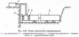 Punching method effective for various soils of groups I ... IV with a diameter of extruded pipelines from 600 to 1720 mm and a laying length of up to 100 m. With this method, the pipe is pressed through the open end into the soil, which, falling into the pipe, forms a dense plug. The soil inside the pipe is being developed different ways and removed from the face.
To create a push force during punching, hydraulic jacks are used, located symmetrically around the circumference of the pipe. Punching is performed in the following sequence. In the pit, equipped with a strong retaining wall and hydraulic jacks, the first link of the extruded pipe is lowered onto the guide frame and joined to the pressure plate of the jacks, leaving the end of the pipe free. When pressed with jacks, the open end of the pipe enters the ground, a soil plug is formed inside the pipe. The pressure plate of the jack returns to its original position, and a gap is formed between the end of the pipe and the plate, equal to the stroke of the jack rods. In the initial period, the soil inside is developed with long-handled shovels (bailers), and later with short-handled shovels and pneumatic percussion devices.
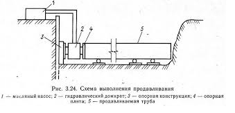
After development and removal of soil from the pipe, the first pressure pipe is installed in the gap between the pressure plate of the jacks and the edge of the pipe being pressed through, the length of which is equal to the pitch of the jack rods. There are three such pressure pipes. The second is twice as long as the first, the third - three times. When a gap equal to four steps of the jack rods is formed between the pressure plate of the jacks and the free end of the pipe, the first and third pressure pipes are installed, with a gap of five steps - the second and third. Installation of more than two pressure pipes in the gap between the pressure plate of the jacks and the free end of the pipe is prohibited. With full penetration into the soil, excavation and removal of soil from the internal cavity of one pipe link, the next link is lowered into the pit and welded to the free end and the cycles continue. The scheme of work on punching the pipeline is shown in fig. 3.24.
When laying the pipeline using the puncture method, the pipe is equipped with a special conical tip. This reduces the friction force and resistance during soil deformation. In some cases, we can use belts with a plug. In the event that the length of the puncture is small, it is carried out by the open end of the pipe.
Choice of equipment for puncture
To select the number and type of pressing devices, we make calculations to determine the required pressing force. It depends on:
- pipe diameter;
- the length of the pipeline to be laid;
- type of soil;
- landscape features.
Puncture forces are different and range from 150-2000 kN. Having calculated the required pressing force, we will be able to decide on the type of thrust wall in the excavated pit and the number of jacks for the power plant.
Necessary equipment for puncture is pressure pump-jacking unit. It consists of GD-170 hydraulic jacks placed on a common frame (one or two paired) with a force of up to 170 tf each. The jack rods have a large stroke amplitude - up to 1.15-1.3 m.
The jacking installation is placed at the bottom of the working pit - a puncture will be carried out from it. Not far from the pit there is a hydraulic pump with a pressure of up to 30 MPa, otherwise 300 kgf / cm2.
Progress
The puncture process itself is a cyclic indentation - the jacks alternately switch to forward and reverse. The impact on the pipe is carried out through the cap with clamping clamps, ramrods or replaceable pressure nozzles.
Using branch pipes with a length of 1 to 4 m, having completely pressed the pipe to the stroke length of the rod, it is returned to its initial position and a double-length branch pipe is placed in the resulting opening.
This process is repeated until the puncture of the first section of the pipeline is completed (typically 6 m). After that, the next link is attached to it and the operation is repeated.
Puncture using a ramrod
Ramrods are pipes with side holes. The distance between these holes is determined by the stroke length of the jack rods. Ramrods are divided into two types: internal (moving inside the casing and having a smaller diameter than the pipe being laid) and external (covering the casing from the outside).
In the process of pushing the first link, with the reverse stroke of the rods, the ramrod is simultaneously pulled back. The rod is moved to the next hole and the steps are repeated until the link is completely pressed in. Having welded the next link, it is pressed in with the same ramrod.
Usually, we carry out puncture of pipelines using jacks in clay and sandy soils that do not have solid inclusions.
Features of the operation of various installations
- Installation of GPU-600 . When laying pipes with a diameter of 104 to 630 mm, the length of which is up to 80 m, on soils of groups I-IV (without large solid inclusions), we use the GPU-600 installation when laying pipes by puncture method. Its principle of operation is called "walking jacks". First, with hydraulic jacks of 1.2 m (stroke length), the workers push the movable pressure plate with the pipe, turning on the oil station. Having completed the working cycle with the reverse stroke of the jacks, the released movable cycle is pulled up after the pipe being laid. These operations are repeated until the first link is introduced into the soil. Then the slide with jacks, the movable stop and the pressure plate take their original position. After that, we mount the next link of the pipeline and the process repeats.
- Installation of Glavmosstroy. Pipes with a diameter of 209 to 426 mm in soils of groups I-IV (regardless of humidity) for a length of up to 45 m should be placed using the Glavmosstroy installation - it works on the same principle of "walking jacks" as GPU-600.
- Ground piercers and pneumatic punchers types IP-4605, PR-400 (or SO-134), PR-60 (or SO-144) and IP-4603 are used by us for laying pipes with a diameter of 63 to 400 mm using a closed method. Pneumatic punchers of the "Mole" type allow you to create wells of any kind (open/closed, inclined/horizontal) with compacted walls up to 40-50 m long. its working body, thus driving it into the ground.
- Hydropuncture. Using the kinetic energy of the water flow, we can pierce pipes using the hydraulic piercing method. At the same time, a jet of water coming out of a special nozzle on the front of the pipe blurs a hole up to 500 mm in diameter. Pipes are laid in it. The water flow is calculated taking into account the head, jet speed and soil type. This method has its own characteristics: work is simplified and the rate of well formation increases to 30 m / shift, but deviations from the design axis are possible and the length of penetration cannot exceed 20-30 m. At the same time, the working conditions themselves become more complicated - the working pit is polluted .
Piercing machines for difficult soils
When laying pipes in quick-moving, incoherent sandy and sandy soils, it is possible to speed up the process by vibropuncture. In special installations of this method, vibration exciters directed longitudinally are used.
Vibropuncture they lay pipes up to 500 mm in diameter for a maximum length of 35 to 60 m, while the penetration rate is up to 20-60 m/h. In the same way, you can also remove pipes from the ground.
Focusing on greater efficiency, we most often use installation UVVGP-400 VNIIGS designs. The principle of operation is as follows: a casing with a tip on one side, the other side is placed in the impact part of the vibratory hammer. Obeying the shock impulses, backed up by static indentation by the loading chain hoist, the pipe moves in the ground.