A welding arc is a powerful, long-term electrical discharge between energized electrodes in a mixture of gases and vapors. The arc is characterized by high temperature and high current density. The welding arc as a consumer of energy and a power source for the arc (welding transformer, generator or rectifier) forms an interconnected energy system.
There are two modes of operation of this system: 1) static, when the values of voltage and current in the system do not change for a sufficiently long time; 2) transient (dynamic), when the values of voltage and current in the system are continuously changing. However, in all cases, the mode of combustion of the welding arc is determined by the current (I D), voltage (U D), the size of the gap between the electrodes (the so-called arc gap) and the connection between them.
In the arc gap I D (Fig. 1, a), there are three regions: anode 1, cathode 2 and arc column 3. The voltage drop in the anodic and cathodic regions is constant for the given welding conditions. The voltage drop per unit length of the arc column is also a constant value. Therefore, the dependence of the arc voltage on its length is linear (Fig. 1, b).
The stability of the welding arc is determined by the relationship between current and voltage. The graphic representation of this dependence (Fig. 2) at a constant arc length is called the static current-voltage characteristic of the arc. The graph clearly shows three main sections: an increase in current in the section I accompanied by a decrease in arc voltage; Location on II arc voltage changes little; Location on III the tension rises. The modes of combustion of the welding arc, corresponding to the first section, are unstable at the voltages of the existing power sources. In practice, the welding arc will be stable in the second and third sections of the current-voltage characteristic. With increasing or decreasing the length of the arc, the characteristics will shift, respectively, to positions 2 and 3 (see Fig. 2). For electrodes with a smaller diameter, the characteristics are shifted to the left, and those of a larger diameter - to the right.

Rice. 1. Welding arc burning between non-consumable electrodes: a - arc diagram, b - dependence of the arc voltage (U) on the arc gap (/ d): 1 - anode region, 2 - cathode region, 3 - arc column

Fig. 2 Current-voltage characteristic of the arc (CVC)
Shown in fig. 2 the current-voltage characteristic of the arc was taken at a constant length of the welding arc. In consumable electrode welding, the length of the arc gap is continuously changing. In these cases, you should use the characteristics that determine the relationship between the voltage and the arc current at a constant feed speed of the electrode wire (Fig. 3, curves 1 and 2). Each feed rate corresponds to a certain range of currents at which the welding arc burns steadily and the electrode melts. In this case, with small changes in current, the voltage changes within wide limits. This dependence is usually called the characteristic of stable performance. It, like the current-voltage characteristic, depends on the length of the electrode stickout and the feed rate.
These regularities are valid for direct and alternating currents, since the type of current does not affect the shape of the current-voltage characteristics of the electric arc. The shape of the characteristic is influenced by the geometry and material of the electrodes, the cooling conditions of the arc column, and the nature of the medium in which the discharge occurs.
The stability of the welding arc and the welding mode depend on the conditions for the existence of the arc discharge and the properties, parameters of power sources and the electrical circuit. The external characteristic of the power source (curve 3 in Fig. 3) is the dependence of the voltage at its terminals on the load current. The following external characteristics of power supplies are distinguished (Fig. 4): falling 1, gently falling 6, rigid 5, increasing 3 and vertical 2. Power supply with one or another external characteristic is selected depending on the welding method. The control device of each source gives a number of external characteristics ("family of characteristics"). The steady-state operating mode of the system: "welding arc - power source" is determined by the intersection point A of the external characteristic of the power source (1, 2, 3, 5 or 6) and the current-voltage characteristic 7 of the welding arc.
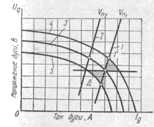
Fig. 3 Current-voltage characteristic of the welding arc (CVC) 1.2 at a constant wire feed speed (characteristic of stable operation) and external characteristics of power sources 3, 4 and 5
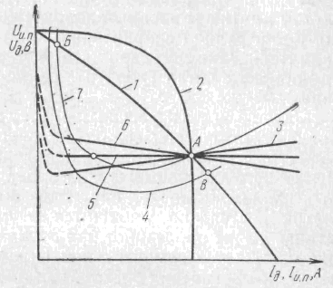
Fig. 4 External characteristics of power sources 1, 2, 3, 5, 6 and current-voltage characteristics of the welding arc 4, 7
The welding process will be stable if for a long time the arc discharge exists continuously at set values voltage and current. As seen from Fig. 4, at points A and B of the intersection of the external characteristics of the arc 7 and the power source, there will be an equilibrium in current and voltage. If, for any reason, the current in the welding arc corresponding to point A decreases, its voltage will be less than the steady-state voltage of the power source; this will lead to an increase in the current, i.e., to a return to point A. On the contrary, with a random increase in current, the steady-state voltage of the power source turns out to be less than the arc voltage; this will lead to a decrease in the current and, consequently, to the restoration of the mode of combustion of the welding arc. From similar reasoning, it is clear that at point B, the welding arc burns unstably. Any random changes in the current develop until it reaches a value corresponding to the point of stable equilibrium A or until the arc is broken. With a gently dipping external characteristic (curve 6), stable burning of the arc will also occur at point A.
When working on a falling section of the current-voltage characteristic of the arc, the external characteristic of the source at the operating point should be steeper than the static characteristic of the welding arc. With increasing characteristics of the arc, the external characteristics of the source can be rigid 5 or even increasing 3.
In manual welding, when changes in arc length are possible, it must have a sufficient safety margin.
All other things being equal, the stability margin increases with an increase in the steepness of the external characteristics of the power source. Therefore, sources with steeply falling characteristics are used for manual welding: the welder can lengthen the arc without fear that it will break, or shorten it without fear of an excessive increase in current.
Self-regulation of the welding arc. In automatic or semi-automatic consumable electrode welding, its feed rate (va) is equal to the melting rate. With a random decrease in the arc gap (curve 4 in Fig. 4), the current increases and the wire begins to melt faster. As a result, the arc gap will gradually increase and the welding arc will reach its original length. The same will happen if the arc is accidentally lengthened. This phenomenon is called self-regulation of the welding arc, since the restoration of the original mode occurs without the influence of any regulator. Self-regulation is the more active, the flatter the external characteristic of the power source and the higher the electrode feed rate. Therefore, for mechanized consumable electrode welding, power sources with gently dipping external characteristics should be selected. When welding with direct current in shielded gases, when the static characteristic of the welding arc acquires an increasing form, it is rational to use sources with a rigid characteristic for self-regulation systems. However, their open-circuit voltage is low and may even be less than the operating voltage of the arc, which makes it difficult to initiate its initial excitation. In these cases, it is desirable to use power supplies in which the external characteristic in the working section is rigid or gently increasing volt-ampere characteristic, and the open circuit voltage is slightly increased, as shown by the dotted line in Fig. 4.
The AC welding arc requires power supplies to reliably re-excite the welding arc. This is achieved by choosing the correct relationship between the no-load voltage, ignition and arc ignition and the parameters of the welding circuit. The simplest way to obtain a stable welding arc is to include reactance in the welding circuit. Due to this, at the moment of re-excitation of the arc, the voltage across the arc can sharply increase (Fig. 5) to the value of the ignition voltage (U3). The dashed t / xx curve represents the no-load voltage of the power supply. Under load, due to the presence of reactance, the welding current lags behind the voltage in time.
When the arc is broken, the voltage across the arc gap should rise to a value corresponding to the instantaneous value of the open circuit voltage of the power source. Due to the lag of the current from the voltage, this voltage is sufficient to re-excite the welding arc (Un).
Metal transfer in the welding arc and requirements for the dynamic properties of power sources. There are the following types of transfer of the electrode metal into the weld pool: coarse droplet, typical for low current densities; fine-droplet, jet, when the metal flows from the electrode in very small drops. Drops of molten metal periodically close the arc gap, or if short circuits do not occur, they periodically change the arc length. At a high current density in the electrode, a fine-drop metal transfer is observed, without noticeable fluctuations in the length and voltage of the welding arc.
Voltage, current and arc length undergo periodic changes from no-load to short-circuit; in the operating mode, the arc burns, the formation and growth of a drop occurs. Subsequently, with a short circuit between the drop and the bath, the current increases sharply. This leads to the compression of the drop and to the destruction of the bridge between the drop and the electrode. The voltage rises almost instantly and the welding arc is re-ignited, i.e. the process is periodically repeated. The change of modes occurs within fractions of a second. Therefore, the power supply must have high dynamic properties, that is, a high voltage rise rate when the circuit is broken and the required current rise rate.
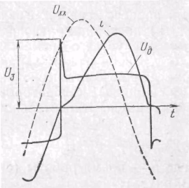
Rice. 5 Oscillogram of current and voltage of the arc when welding with alternating current.
At a low rate of current rise, an unmelted wire enters the bath. It heats up relatively slowly in a large area, which then collapses. If the current rises too quickly, the bridge between the bath and the electrode metal droplet quickly overheats and explosively collapses. Some of the molten metal splashes out and does not enter the seam.
To avoid splashing, it is necessary to increase the electromagnetic inertia of the power source by increasing the inductance of the welding circuit.
Physical foundations of welding materials
Welding is the process of joining various solid materials at high temperatures. Its essence lies in the emergence of atomic-molecular bonds between the structural components of the connecting products. It was designed to combine the metal surfaces of various parts. Therefore, its essence and mechanism will be considered on metallic materials.
The process can be carried out in two ways: melting and pressure.
The first is that the temperature in the area of joining the metal surfaces is brought to the corresponding melting points and each of them melts. The two liquid metals then merge together to form a common weld pool, which, when cooled, crystallizes to form a hard interlayer called a weld.
In the second, at high pressure, the metal experiences increased plastic deformation and it begins to flow like a liquid. Then everything happens as in the previous case.
Each of the above methods, in turn, is classified according to the principle of its implementation.
Fusion welding should include and soldering, characterized in that only the filler material is melted, and the base metal to be welded remains unmelted, while the base metal is partially melted during welding.
The dominant position in the production of metal structures for the last 70 years has been arc welding. She carries out more than 60% of the total volume of welding. There is no other method yet that can compete with arc welding in its simplicity and versatility.
In 1881, N. N. Benardos discovered arc welding. In 1888 - 1890 Russian engineer N.G. Slavyanov developed and patented arc welding with a metal electrode, which is at the same time a filler material. In 1907 - Swedish engineer O. Kjelberg used coated metal electrodes, which made it possible to improve the quality of welded joints.
A welding arc is a powerful electrical discharge between electrodes in an environment of ionized gases and vapors.
According to the method of influencing the metal during the welding process, the arc can be indirect (independent) and direct (dependent) action. In the first case, the base metal is not included in the welding circuit and is heated mainly due to heat transfer from the arc gases and its radiation. This method is currently not used in the industry.
Classification of welding methods
When welding with a direct arc, the metal belongs to the elements of the welding circuit and acts as one of the electrodes. It is heated mainly by bombarding its surface with electrically charged particles. The specific heating power of the metal surface in this case in the region of the electrode spot is very high and ranges from 10 3 to 10 5 W / cm 2.
Welding is carried out with consumable and non-consumable electrodes. The first is called welding according to the method of N.G. Slavyanov, and the second - according to the method of N.N.Benardos.
Consumable electrodes are made from steel, aluminum and some other metals. They also play the role of filler material, of which the welded metal seam is largely composed. Carbon (graphite) or tungsten electrodes are non-consumable and do not take part in the formation of the seam. In this case, the filler material is additionally introduced from the side in the form of a wire or rod.
DC or AC, single or multiphase currents, low or high frequency can be used to power the arc; it is possible to use complicated combined schemes.
When welding, the following mode is used: U d = 10 - 50 V; = 1 - 3000 A; R d = 0.01 - 150 kW, where I d is the current strength, U d is the voltage and R d is the arc power.
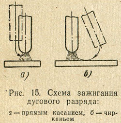
The arc is ignited by short-term short-circuiting of the electrode to the product. Short-circuit current (SC) almost instantly melts the metal at the point of contact, resulting in the formation of a liquid bridge. When the electrode is withdrawn, it stretches, the metal overheats and its temperature reaches the boiling point; metal vapors and gases under the influence of thermal and field emission are ionized - an arc is initiated. When welding with a non-consumable electrode, the arc is excited in an uncontrolled way, ionizing with high-frequency pulses.
The bases of the arc are sharply outlined, brightly glowing spots on the surface of the electrodes. The entire current passes through them, the density of which can reach several hundred amperes per 1 mm 2. In a DC arc, a distinction is made between cathode and anode spots. The electrically conductive gas channel between the spots is a plasma - a mixture of neutral atoms, electrons and ions from the atmosphere surrounding the arc, and from the substances that make up the electrodes and fluxes. It has a frusto-conical shape and is subdivided into 3 areas: cathode length of the order of 10 -3 - 10 -4 mm, anode- with a thickness of 10 -2 - 10 -3 mm and an arc pillar. The arc post is the longest and highest temperature zone. The temperature at its axis reaches 6000 - 8000 K. The temperature of the spots is much lower - it is usually close to the boiling points of the electrode material (for steel - 3013 K). Therefore, in both regions, the temperature gradient is very high (about 3 × 10 6 K / mm), which creates a powerful heat flux from the arc column to the cathode and anode spots.
In the arc column, the voltage drop is small; the field strength in it is only 1 - 5 V / mm and is almost independent of the length. A significant part of the arc voltage drops in the near-electrode regions; 4 - 5 V in the anodic region and from 2 to 20 V in the cathodic region. The length of the regions is small; therefore, the field strength in them reaches 2 × 10 5 and 10 3 V / mm, respectively.
The power released in the arc column is determined by the field strength, the arc current, and the length of the column. It is partially spent on heating the metal, to some extent - it is scattered by radiation into space. The deeper the arc penetrates into the welded metal, the lower the radiation losses of the column and the higher the coefficient useful action arc (efficiency).
The arc voltage, i.e. the potential difference between the electrodes, depends on the arc length, current strength, as well as on the materials and dimensions of the electrodes and the composition of the arc plasma.
The dependence of the arc voltage on the current strength at a constant arc length is called the static volt-ampere or simply the static characteristic of the arc. It is nonlinear and consists of three sections - falling I, rigid II, and rising III. For an arc with a length of 4 mm with a consumable steel electrode with a diameter of 4 mm, the boundary of the falling section is about 40 - 50 A, and the hard one is about 350 A.
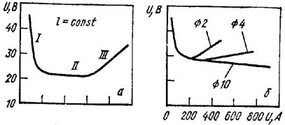
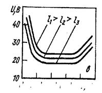
Static characteristic of the welding arc:
At low currents (section I in Fig. 13.4, a), the heat fluxes from the near-electrode regions to the electrode spots are insufficient to heat the latter to the boiling points of the electrode material. Therefore, the temperature difference between the arc column and the electrode spots is very large, which means that the voltage drop in the near-electrode regions is also large. At the same time, the decrease in U in the column is also significant, since it is relatively "cold" and the degree of gas ionization is small. Therefore, a high voltage is required to burn an arc at low currents. With an increase in the current strength, the heating temperatures of the electrode spots and the arc column increase, which means that the drop in U in the near-electrode regions and in the arc column decreases. As a result, the arc voltage decreases with increasing current strength and the characteristic turns out to be falling.
A change in the current strength in the region of average values is accompanied by a proportional modification of the arc column cross section and the areas of both spots (their diameter is smaller than that of the electrode). The current density in the column does not change, and the arc voltage as a whole remains constant.
In the zone of high currents, the cathode spot overlaps the entire end of the electrode, the increase in current strength occurs not due to an increase in the area of the conductive channel, but due to an increase in density. Therefore, to increase the current strength, it is necessary to raise the voltage, and the relationship between them is almost linear. The smaller the diameter of the electrode, the lower the current at which the arc characteristic becomes increasing. At a constant current strength, the arc voltage is almost linearly dependent on its length:
U d = a + bl,
where a- the sum of the voltage drops in the cathode and anode regions; l- arc length; b- tension (voltage gradient) of the arc column. For steel electrodes a= 8 - 25 V; b= 2.3 - 4.3 V / mm. Therefore, an increase in the length of the arc, other things being equal, leads to a shift of its static characteristic upward, a decrease - downward, since the voltage drop in the arc column changes in proportion to its length (Fig. 13.4, c).
The welding arc can be operated with direct and alternating current. The arc is supplied with alternating current from a welding transformer, with direct current from welding rectifiers and generators. Most generators are collector driven by three phases asynchronous motor or from an internal combustion engine. A generator complete with a drive from an asynchronous motor is called a welding converter, and from an internal combustion engine - a unit. The latter are used mainly for welding in the field, where there are no power grids.
Most sources are designed to supply current to one welding station. But in workshops with a large number of welding stations, it is more economical to use multi-station sources that feed several stations at the same time.
Direct current has certain technological advantages over alternating current. The arc burns more steadily on it. By changing its polarity, you can adjust the ratio between the intensity of heating the electrode and the product. Therefore, for a long time it was believed that high-quality welded joints can only be obtained with direct current. However, modern electrodes make it possible to obtain high-quality seams on most materials with alternating current. The use of alternating current to power the arc has several advantages. The main one is efficiency. The efficiency of the welding transformer is about 0.9; rectifier - about 0.7; and a converter with a collector generator is approximately 0.45.
Thus, welding with alternating current is twice energetically more profitable than working with a converter. In addition, the welding transformer is significantly more reliable, easier to operate and lighter than DC power supplies. Therefore, most of the volume of arc welding is performed with alternating current.
The external volt-ampere or simply the external characteristic of the arc power source is the relationship between the current and the voltage at its output at steady state. It can be steep and gently dipping, rigid and ascending. Different welding processes require power supplies with different external characteristics.

External characteristics of power supplies:
1, 2 - steeply and gently dipping; 3 - hard; 4 - increasing
For manual arc welding with both consumable and non-consumable electrodes, only power sources with steeply dipping characteristics are required. Arc length fluctuations are typical for manual welding. Therefore, in order for the dimensions of the weld pool and the cross-section of the seam to be constant, it is necessary to ensure that the current remains constant with changes in the arc length. This is achieved by using a power supply with a steeply falling characteristic.
When the arc is on, the current and voltage at the output of the power supply are equal to those of the arc. The arc burning mode is determined by the intersection point of the corresponding external and static characteristics. In fig. 13.6, and there are two such points, but the arc will burn steadily only at a steady state corresponding to point B. This is explained as follows. If, for some random reason, the arc current decreases, then the voltage of the source will become greater than U d and cause an increase in I in the circuit, i.e., return to point B. If the arc current increases, then its voltage will be greater than that of the power source, which again will lead to point B.
Thus, the equilibrium corresponding to this point in the arc - source system is self-aligning. Similar reasoning shows that the slightest deviation of the arc mode from point A develops either until the arc is broken or before the transition to point B.

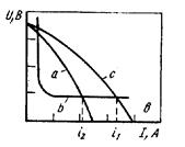
External characteristic of the power supply (a, c)
and static characteristic of the arc in manual arc welding (b)
Thus, for stable burning of the arc, it is necessary that the steepness of the fall of the external characteristic of the source should be greater than the steepness of the fall of the static characteristic of the arc at the point of their intersection.Consequently, when operating in modes corresponding to the falling section of the static characteristic of the arc, the external characteristic of the source should be even more steeply dipping. When operating in modes corresponding to an almost horizontal section of the static characteristic of the arc, it will burn steadily both with a steeply falling and a gently falling characteristic of the source. If the arc mode corresponds to the ascending section of the static characteristic, then the arc stability is ensured for any characteristic - steeply dipping, gently dipping, rigid and ascending. In practice, additional restrictions on the type of characteristic are imposed by the device of the wire electrode feed mechanism in mechanized welding. Depending on it, power supplies with rigid or gently dipping characteristics are used.
When the arc length changes, its static characteristic shifts up or down and, accordingly, the point of intersection of the static arc characteristic with the external characteristic of the source, that is, the current mode, also shifts. But the magnitude of the arc current change during manual welding does not exceed a few percent, since the characteristic of the power source is steeply dipping.
A welding arc is a powerful, stable electric discharge in a gaseous medium formed between the electrodes, or between the electrodes and the workpiece. The welding arc is characterized by the release of a large amount of heat energy and a strong light effect. It is a concentrated heat source and is used to melt base and filler materials.
Depending on the environment in which the arc discharge occurs, a distinction is made between:
an open arc burning in the air, where the composition of the gaseous medium of the arc zone is air with an admixture of vapors of the metal being welded, the material of the electrodes and electrode coatings;
closed arc burning submerged arc, where the composition of the gaseous medium of the arc zone are vapors of the base metal, wire and protective flux;
arc burning with protective gases(the composition of the gaseous medium of the arc zone includes the atmosphere of a shielding gas, a pair of wire and base metal). The welding arc is classified by the type of current used (direct, alternating, three-phase) and by the duration of burning (stationary, pulsed). When using direct current, a direct arc is distinguished and reverse polarity... With straight polarity, the negative pole of the power circuit, the cathode, is on the electrode, and the positive pole, the anode, is on the base metal. With reverse polarity, plus is on the electrode, and minus is on the product.
Depending on the type of electrode used, the arc can be struck between consumable (metal) and non-consumable (carbon, tungsten, etc.) electrodes. According to the principle of operation, arcs are of direct, indirect and combined action (Fig. 14).
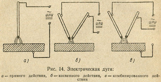
Straight arc called the arc discharge that occurs between the electrode and the product. Indirect arc is an arc discharge between two electrodes (atomic hydrogen welding). Combined arc is a combination of a direct and indirect arc. An example of a combined arc is a three-phase arc in which two arcs electrically connect the electrodes to the workpiece, and the third is lit between two electrodes that are isolated from each other.
The arc is excited in two ways: by touching or striking, the essence of which is shown in Fig. 15.
In a welding arc, the arc gap is divided into three main areas: anode, cathode and arc column. In the process of arc burning, there are active spots on the electrode and base metal, which are more heated sections of the electrode and base metal, through which the entire arc current passes. The active spot located on the cathode is called cathodic, and the spot on the anode is anode.

The total length of the welding arc (Fig. 16) is equal to the sum of the lengths of all three areas:
L d = L to + L with + L a,
where L d - the total length of the welding arc, cm;
L k - the length of the cathode region, equal to approximately 10 -5 cm;
L c - the length of the arc column, cm;
L d - the length of the anode region, equal to approximately 10 -3 ÷ 10 -4 cm.
The total voltage of the welding arc is the sum of the voltage drops in individual areas of the arc:
U d = U to + U with + U a,
where U d is the total voltage drop across the arc, v;
U k - voltage drop in the cathode region, v;
U c - voltage drop in the arc column, v;
U a - voltage drop in the anode area, v.
The temperature in the arc column ranges from 5000 to 12000 ° K and depends on the composition of the gas medium of the arc, material, electrode diameter and current density. The temperature can be approximately determined by the formula proposed by Academician of the Academy of Sciences of the Ukrainian SSR K.K. Khrenov:
T st = 810 U ef,
where T st is the temperature of the arc column, ° K;
U eff is the effective ionization potential.
Static current-voltage characteristic of the welding arc. The dependence of the voltage in the welding arc on its length and the value of the welding Current, called the current-voltage characteristic of the welding arc, can be described by the equation
U d + a + bL d,
where a- the sum of voltage drops at the cathode and anode ( a = U to + U a):
b- specific voltage drop in the gas column, referred to 1 mm arc length (value b depends on the gas composition of the arc column);
L d - arc length, mm.
At low and ultrahigh currents U d depends on the value of the welding current.
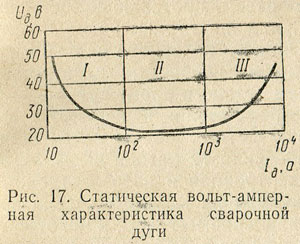
The static current-voltage characteristic of the welding arc is shown in Fig. 17. In the area I increase in current to 80 a leads to a sharp drop in arc voltage, which is due to the fact that with low-power arcs, an increase in current causes an increase in the sectional area of the arc column, as well as its electrical conductivity. The shape of the static characteristic of the welding arc in this section is falling. A welding arc with a falling current-voltage characteristic has low stability. In the area of II (80 - 800 a) the arc voltage almost does not change, which is explained by an increase in the section of the arc column and active spots in proportion to the change in the value of the welding current, therefore, the current density and voltage drop in all sections of the arc discharge remain constant. In this case, the static characteristic of the welding arc is rigid. This arc is widely used in welding technology. With an increase in the welding current of more than 800 a(region III) the arc voltage rises again. This is explained by an increase in the current density without the growth of the cathode spot, since the electrode surface is already insufficient to accommodate a cathode spot with a normal current density. The rising arc is widely used in submerged arc and gas shielded welding.
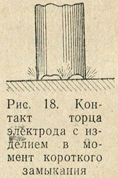
Processes occurring at the moment of initiation of the welding arc. In the event of a short circuit, the end of the electrode comes into contact with the product. Since the end face of the electrode has an uneven surface, the contact does not occur along the entire plane of the end face of the electrode (Fig. 18). At the points of contact, the current density reaches very high values, and under the action of the released heat at these points, the metal instantly melts. At the moment the electrode is removed from the product, the zone of molten metal - the liquid bridge is stretched, the cross section decreases, and the temperature of the metal increases. When the electrode is removed from the product, the liquid metal bridge breaks, and rapid evaporation ("explosion" of the metal) occurs. At this moment, the discharge gap is filled with heated ionized particles of metal vapors, electrode coating and air - a welding arc arises. The arcing process takes only a fraction of a second. The ionization of gases in the arc gap at the initial moment occurs as a result of thermionic emission from the cathode surface, due to structural disturbances as a result of abrupt overheating and melting of the metal and electrode coating.
An increase in the density of the electron flux also occurs due to oxides and the formed surface layers of molten fluxes or electrode coatings, which reduce the work function of electrons. At the moment of rupture of the liquid metal bridge, the potential drops sharply, which contributes to the formation of field emission. The drop in potential makes it possible to increase the emission current density, accumulate kinetic energy for electrons for inelastic collisions with metal atoms and transfer them into an ionized state, thereby increasing the number of electrons and, consequently, the conductivity of the arc gap. As a result, the current increases and the voltage drops. This happens up to a certain limit, and then a steady state of the arc discharge begins - the burning of the arc.
Cathode region. The processes occurring in the area of cathodic voltage drop play an important role in welding processes. The region of the cathode voltage drop is a source of primary electrons, which maintain the gases of the arc gap in an excited ionized state and carry on themselves, due to their high mobility, the bulk of the charge. The detachment of electrons from the cathode surface is caused primarily by thermionic and field emission. The energy spent on the extraction of electrons from the cathode surface and metal deposition is to some extent compensated for by the energy from the arc column due to the flow of positively charged ions, which give up their ionization energy on the cathode surface. The processes occurring in the region of the cathode voltage drop can be represented as follows.
1. Electrons, being emitted from the cathode surface, receive accelerations necessary for ionization of gas molecules and atoms. In some cases, the cathode voltage drop is equal to the ionization potential of the gas. The magnitude of the cathode voltage drop depends on the ionization potential of the gas and is 10 - 16 v.
2. Due to the small thickness of the cathode zone (about 10 -5 cm) electrons and ions in it move without collisions and it is approximately equal to the free path of an electron. The values of the thickness of the cathode zone, found empirically, are less than 10 -4 cm.
3. With an increase in the current density, the temperature of the cathode region rises.
Arc pillar. There are three kinds of charged particles in the arc column - electrons, positive ions and negative ions, which move to the opposite pole.
The arc column can be considered neutral, since the sum of the charges of negative particles is equal to the sum of the charges of positive particles. The arc column is characterized by the formation of charged particles and the reunification of charged particles into neutral atoms (recombination). The flow of electrons through the gas layer of the discharge gap mainly causes elastic collisions with gas molecules and atoms, as a result of which a very heat... Ionization is also possible as a result of inelastic collisions.
The temperature of the arc column depends on the composition of the gases, the magnitude of the welding current (with an increase in the magnitude of the current, the temperature rises), the type of electrode coatings and polarity. With reversed polarity, the arc column temperature is higher.
Anode region. The anode region is longer and has a lower voltage gradient than the cathode region. The voltage drop in the anode region is created as a result of the extraction of electrons from the arc discharge column and their acceleration when they enter the anode. In the anodic region, there is mainly only an electron current, due to the small number of negatively charged ions, which have lower velocities than the electron. An electron hitting the anode surface gives up to the metal not only the stock of kinetic energy, but also the energy of the work function, therefore the anode receives energy from the arc column not only in the form of a stream of electrons, but also in the form of thermal radiation. As a result, the temperature of the anode is always higher and more heat is generated on it.
Features of the welding arc supplied with alternating current. When welding with an AC arc (power frequency 50 periods per second), the cathode and anode spots are swapped 100 times per second. When the polarity changes, the so-called "valve effect" is formed, which consists in partial rectification of the current. The current is rectified as a result of continuously changing electron emission, since when the direction of the current changes, the conditions for the emission of currents from the electrode and from the product will not be the same.
With the same materials, the current is almost not rectified, the rectification of the current in the welding arc is called DC component, which in argon-arc welding of aluminum has a negative effect on the process. The stability of burning of a welding arc supplied with alternating current is lower than that of an arc supplied with direct current. This is due to the fact that in the process of current zero crossing and polarity reversal at the beginning and end of each half-period, the arc is extinguished. At the moment of extinction of the arc, the temperature of the arc gap decreases, causing deionization of the gases in the arc column. At the same time, the temperature of active spots also drops. The temperature drops especially at that active spot located on the surface of the weld pool due to heat transfer to the product. Due to the thermal inertia of the process, the temperature drop lags somewhat in phase from the current zero crossing. Ignition of the arc due to the reduced ionization of the arc gap at the beginning of each half-cycle is possible only with an increased voltage between the electrode and the workpiece, called the ignition peak. If the cathode spot is located on the base metal, then in this case the magnitude of the ignition peak is slightly higher. The magnitude of the ignition peak is influenced by the effective ionization potential: the larger the effective ionization potential, the higher the ignition peak must be. If there are easily ionizable elements in the welding arc, the ignition peak decreases and, conversely, it increases when fluorine ions are present in the arc atmosphere, which, when combined with positive ions, easily form neutral molecules.
The main advantages of an alternating current arc include: relative simplicity and lower cost of equipment, the absence of magnetic blast and the presence of cathodic sputtering of an oxide film in argon-arc aluminum welding. Cathode sputtering is the process of bombarding the weld pool with positive ions at the moment when the product is the cathode, due to which the oxide film is destroyed.
Influence magnetic field and ferromagnetic masses per welding arc
In a welding arc, the arc column can be viewed as a flexible conductor through which an electric current flows and which, under the influence of an electromagnetic field, can change its shape. If conditions are created for the interaction of the electromagnetic field that occurs around the welding arc with extraneous magnetic fields, with the own field of the welding circuit, as well as with ferromagnetic materials, then in this case a deviation of the arc discharge from the original intrinsic axis is observed. In this case, the welding process itself is sometimes disrupted. This phenomenon is called magnetic blast.
Let's look at a few examples showing the effect of an external magnetic field on a welding arc.
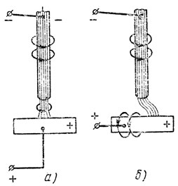
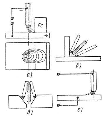
1. If a symmetrical magnetic field is created around the arc, then the arc does not deflect, since the created field has a symmetrical effect on the arc column (Fig. 19, a).

2. An asymmetric magnetic field acts on the welding arc column, which is created by the current flowing in the product; in this case, the arc column will deviate in the direction opposite to the current lead (Fig. 19.6).
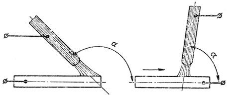
The angle of inclination of the electrode is also essential, which also causes deflection of the arc (Fig, 20).

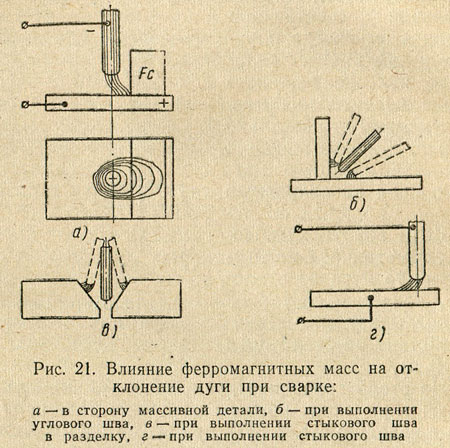
A strong factor acting on the deflection of the arc are ferromagnetic masses: massive welded Products (ferromagnetic masses) have a higher magnetic permeability than air, and magnetic lines of force they always strive to pass through the medium that has a lower resistance, therefore, the arc discharge, located closer to the ferromagnetic mass, always deviates in its direction (Fig. 21).
The influence of magnetic fields and ferromagnetic masses can be eliminated by changing the location of the current supply, the angle of inclination of the electrode, by temporarily placing the ferromagnetic material to create a symmetric field and replacing the direct current with alternating current.
Transfer of molten metal through the arc space
During the transfer of molten metal, the forces of gravity, surface tension, electromagnetic field and internal pressure of gases act.
The force of gravity manifests itself in the tendency of the drop to move downward under its own weight. When welding in the lower position, the force of gravity plays a positive role in the transfer of the drop to the weld pool; when welding in vertical and especially in overhead positions, it complicates the process of transferring the electrode metal.
Surface tension force manifests itself in the desire of a liquid to reduce its surface under the influence of molecular forces that tend to give it a shape that would have a minimum energy supply. This form is a sphere. Therefore, the force of surface tension gives the drop of molten metal the shape of a ball and retains this shape until it touches the surface of the molten bath or detaches from the end of the electrode without contact, after which the surface tension of the metal of the bath "pulls" the drop into the bath. The force of surface tension helps to retain the liquid metal of the pool during welding in the overhead position and creates favorable conditions for the formation of the seam.
The strength of the electromagnetic field consists in the fact that the electric current, passing through the electrode, forms a magnetic force field around it, which exerts a compressive effect on the electrode surface, tending to reduce the cross-section of the electrode. The magnetic force field does not affect solid metal. Magnetic forces acting normally to the surface of a spherical molten drop have a significant effect on it. With an increase in the amount of molten metal at the end of the electrode under the action of surface tension forces, as well as compressive magnetic forces, an isthmus forms in the area between the molten and solid electrode metal (Fig. 22).

As the cross-section of the isthmus decreases, the current density sharply increases and the compressive effect of magnetic forces, tending to detach the drop from the electrode, increases. The magnetic forces have a minimal compressive effect on the spherical surface of the droplet facing the molten bath. This is due to the fact that the current density in this part of the arc and on the product is small, therefore, the compressive effect of the magnetic force field is also small. As a result, the metal is always transferred in the direction from the small electrode (rod) to the large electrode (product). It should be noted that in the formed isthmus, due to an increase in resistance during the passage of current, a large amount of heat is released, leading to strong heating and boiling of the isthmus. The metal vapors formed during this overheating at the moment of detachment of the drop have a reactive effect on it - they accelerate its transition to the bath. Electromagnetic forces promote metal transfer in all spatial welding positions.
Internal gas pressure force arises as a result of chemical reactions, which are more active, the more the molten metal at the end of the electrode is overheated. The initial products for the formation of reactions are gases, and the volume of the gases formed is tens of times greater than the volume of the compounds involved in the reaction. The separation of large and small drops from the end of the electrode occurs as a result of violent boiling and removal of the formed gases from the molten metal. The formation of splashes on the base metal is also explained by the explosive fragmentation of the drop when the drop passes through the arc gap, since at this moment the release of gases from it intensifies, and some part of the drop flies out of the weld pool. The force of the internal pressure of the gases mainly moves the droplet from the electrode to the workpiece.
The main indicators of the welding arc
Melting coefficient. When welding metal, the seam is formed due to melting of the filler and penetration of the base metal.
Filler metal melting is characterized by a melting coefficient
where α p is the melting coefficient;
G p is the weight of the melted over time t electrode metal, G
t- arc burning time, h;
I- welding current, a.
§ 32. Welding properties of the arc
The welding arc is characterized by the release of a large amount of heat energy and a strong light effect. It is a concentrated heat source and is used to melt base and filler materials.
Depending on the environment in which the arc discharge occurs, there are: an open arc burning in air, where the composition of the gaseous medium of the arc zone is air mixed with vapors of the metal being welded, the material of the electrodes and electrode coatings;
a closed arc burning under a submerged arc, where the composition of the gaseous medium of the arc zone is the vapor of the base metal, wire and protective flux;
an arc burning in an environment of protective gases - a closed arc (the atmosphere of the arc zone includes the atmosphere of a protective gas, vapor of the molten metal of the wire and the base metal). The welding arc is classified by the type of current used (direct, alternating, three-phase) and by the duration of burning (stationary, pulsed). When using direct current, a distinction is made between an arc of direct and reverse polarity. With straight polarity, the negative pole of the power circuit, the cathode, is on the electrode, and the positive pole, the anode, is on the base metal. With reverse polarity, plus is on the electrode, and minus is on the product.
Depending on the type of electrode used, the arc can be initiated between melting (metal) and non-melting (carbon, tungsten, etc.) electrodes. According to the principle of operation, arcs are of direct, indirect and combined action (Fig. 31).
A direct arc is an arc discharge that occurs between an electrode and a workpiece. An indirect arc is an arc discharge between two electrodes (hydrogen atomic welding). A combined bow is a combination of a direct and indirect bow. An example of a combined arc is a three-phase arc in which two arcs electrically connect the electrodes to the workpiece, and the third is lit between two electrodes that are isolated from each other.


The arc is excited in two ways: by touching or striking, the essence of which is shown in Fig. 32.
In a welding arc, the arc gap is divided into three main areas: anode, cathode and arc column. In the process of arc burning, there are active spots on the electrode and base metal, which are more heated sections of the electrode and base metal, through which the entire arc current passes. The active spot on the cathode is called the cathode, and the spot on the anode is called the anode one.
The total length of the welding arc (Fig. 33) is equal to the sum of the lengths of all three areas L D = L K + L C + L a, where L d is the total length of the welding arc, cm; L to - the length of the cathode region, equal to about 10 -5 cm; L c - the length of the arc column, cm; L a - the length of the anode region, equal to approximately - 10 -3 ÷ 10 -4 cm.
The total voltage of the welding arc is composed of the sum of the voltage drops in individual areas of the arc U d = U K + U c + U a, where U d is the total voltage drop across the arc, V; U K - voltage drop in the cathode region, V; U c - voltage drop in the arc column, V; U a - voltage drop in the anode area, V.
The temperature in the arc column ranges from 5000 to 12000 K and depends on the composition of the arc gas medium, material, electrode diameter and current density. The temperature can be approximately determined by the formula proposed by the academician of the Academy of Sciences of the Ukrainian SSR KK Khrenov T st = 810 * U action, where T st is the temperature of the arc column, K; U effective - effective ionization potential.
Static current-voltage characteristic of the welding arc... The dependence of the voltage in the welding arc on its length and the value of the welding current, called the volt-ampere characteristic of the welding arc, can be described by the equation U d = a + bL d, where a is the sum of the voltage drops at the cathode and anode (a = U k + U a); b is the specific voltage drop in the gas column, referred to 1 mm of the arc length (the value of b depends on the gas composition of the arc column); L d - arc length, mm.
At small and ultra-high values of the current U d depends on the value of the welding current.
The static current-voltage characteristic of the welding arc is shown in Fig. 34. In region I, an increase in current to 80 A leads to a sharp drop in arc voltage, which is due to the fact that with low-power arcs, an increase in current causes an increase in the sectional area of the arc column, as well as its electrical conductivity. The shape of the static characteristic of the welding arc in this section is falling. A welding arc with a falling current-voltage characteristic has low stability. In region II (80 - 800 A), the arc voltage remains almost unchanged, which is explained by an increase in the section of the arc column and active spots in proportion to the change in the value of the welding current, therefore, the current density and voltage drop in all sections of the arc discharge remain constant. In this case, the static characteristic of the welding arc is rigid. This arc is widely used in welding technology. When the welding current is increased to more than 800 A (region III), the arc voltage rises again. This is explained by an increase in the current density without the growth of the cathode spot, since the electrode surface is already insufficient to accommodate a cathode spot with a normal current density. The rising arc is widely used in submerged arc and gas shielded welding.
Processes occurring at the moment of initiation of the welding arc... In the event of a short circuit, the end of the electrode comes into contact with the product. Since the end face of the electrode has an uneven surface, contact does not occur over the entire plane of the end face of the electrode (Fig. 35). At the points of contact, the current density reaches very high values and under the action of the released heat at these points, the metal instantly melts. At the moment the electrode is removed from the product, the zone of molten metal - the liquid bridge is stretched, the cross section decreases, and the temperature of the metal increases. When the electrode is removed from the product, the liquid metal bridge breaks, and rapid evaporation ("explosion" of the metal) occurs. At this moment, the discharge gap is filled with heated ionized particles of metal vapors, electrode coating and air - a welding arc arises. The arcing process takes only a fraction of a second. The ionization of gases in the arc gap at the initial moment occurs as a result of thermionic emission from the cathode surface, due to structural disruption as a result of abrupt overheating and melting of the metal and electrode coating.

![]()
An increase in the density of the electron flux also occurs due to oxides and the formed surface layers of molten fluxes or electrode coatings, which reduce the work function of electrons. At the moment of rupture of the liquid metal bridge, the potential drops sharply, which contributes to the formation of field emission. The drop in potential makes it possible to increase the emission current density, accumulate kinetic energy for electrons for inelastic collisions with metal atoms and transfer them into an ionized state, thereby increasing the number of electrons and, consequently, the conductivity of the arc gap. As a result, the current increases and the voltage drops. This happens up to a certain limit, and then a steady state of the arc discharge begins - the burning of the arc.
Cathode region... The processes occurring in the area of cathodic voltage drop play an important role in welding processes. The region of the cathode voltage drop is a source of primary electrons, which maintain the gases of the arc gap in an excited ionized state and carry on themselves, due to their high mobility, the bulk of the charge. The detachment of electrons from the cathode surface is caused primarily by thermionic and field emission. The energy spent on the extraction of electrons from the cathode surface and metal deposition is to some extent compensated for by the energy from the arc column due to the flow of positively charged ions, which give up their ionization energy on the cathode surface. The processes occurring in the region of the cathode voltage drop can be represented as follows.
1. Electrons, being emitted from the cathode surface, receive accelerations necessary for ionization of gas molecules and atoms. In some cases, the cathode voltage drop is equal to the ionization potential of the gas. The magnitude of the cathode voltage drop depends on the ionization potential of the gas and is 10 -16 V.
2. Due to the small thickness of the cathode zone (about 10 -5 cm), electrons and ions in it move without collisions and it is approximately equal to the free path of an electron. The values of the thickness of the cathode zone, found empirically, are less than 10-4 cm.
3. With an increase in the current density, the temperature of the cathode region rises.
Arc pillar... There are three kinds of charged particles in the arc column - electrons, positive ions and negative ions, which move to the opposite pole.
The arc column can be considered neutral, since the sum of the charges of negative particles is equal to the sum of the charges of positive particles. The arc column is characterized by the formation of charged particles and the reunification of charged particles into neutral atoms (recombination). The flow of electrons through the gas layer of the discharge gap mainly causes elastic collisions with gas molecules and atoms, as a result of which a very high temperature is created. Ionization is also possible as a result of inelastic collisions.
The temperature of the arc column depends on the composition of the gases, the magnitude of the welding current (with an increase in the magnitude of the current, the temperature rises), the type of electrode coatings and polarity. With reversed polarity, the arc column temperature is higher.
Anode region... The anode region is longer and has a lower voltage gradient than the cathode region. The voltage drop in the anode region is created as a result of the extraction of electrons from the arc discharge column and their acceleration when they enter the anode. In the anodic region, there is mainly only an electron current, due to the small number of negatively charged ions, which have lower velocities than the electron. An electron hitting the anode surface gives up to the metal not only the stock of kinetic energy, but also the energy of the work function, therefore the anode receives energy from the arc column not only in the form of a stream of electrons, but also in the form of thermal radiation. As a result, the temperature of the anode is always higher and more heat is generated on it.
Features of the welding arc supplied with alternating current... When welding with an AC arc (power frequency 50 periods per second), the cathode and anode spots are swapped 100 times per second. When the polarity is reversed, the so-called "valve effect" is formed, which consists in partial rectification of the current. The current is rectified as a result of continuously changing electron emission, since when the direction of the current changes, the conditions for the emission of currents from the electrode and from the product are not the same.
With the same materials, the current is almost not rectified, the rectification of the current in the welding arc is called the DC component, which, in argon-arc welding of aluminum, has a negative effect on the process. The stability of burning of a welding arc supplied with alternating current is lower than that of an arc supplied with direct current. This is due to the fact that in the process of current zero crossing and polarity reversal at the beginning and end of each half-period, the arc is extinguished. At the moment of extinction of the arc, the temperature of the arc gap decreases, causing deionization of the gases in the arc column. At the same time, the temperature of active spots also drops. The temperature drops especially at that active spot located on the surface of the weld pool due to heat transfer to the product. Due to the thermal inertia of the process, the temperature drop lags somewhat in phase from the current zero crossing. Ignition of the arc due to the reduced ionization of the arc gap at the beginning of each half-cycle is possible only with an increased voltage between the electrode and the workpiece, called the ignition peak. If the cathode spot is located on the base metal, then in this case the magnitude of the ignition peak is slightly higher. The magnitude of the ignition peak is influenced by the effective ionization potential: the larger the effective ionization potential, the higher the ignition peak must be. If there are easily ionizable elements in the welding arc, the ignition peak decreases and, conversely, it increases when fluorine ions are present in the arc atmosphere, which, when combined with positive ions, easily form neutral molecules.
The main advantages of an alternating current arc include: relative simplicity and lower cost of equipment, the absence of magnetic blast and the presence of cathodic sputtering of an oxide film in argon-arc aluminum welding. Cathode sputtering is the process of bombarding the weld pool with positive ions at the moment when the product is the cathode, due to which the oxide film is destroyed.
Influence of magnetic field and ferromagnetic masses on the welding arc
In a welding arc, the arc column can be viewed as a flexible conductor through which an electric current flows and which, under the influence of an electromagnetic field, can change its shape. If conditions are created for the interaction of the electromagnetic field that occurs around the welding arc, with extraneous magnetic fields, with the own field of the welding circuit, as well as with ferromagnetic materials, then in this case a deviation of the arc discharge from the original intrinsic axis is observed. In this case, the welding process itself is sometimes disrupted. This phenomenon is called magnetic blast.
Let's look at a few examples showing the effect of an external magnetic field on a welding arc.
1. If a symmetric magnetic field is created around the arc, then the arc does not deflect, since the created field has a symmetrical effect on the arc column (Fig. 36, a).
2. An asymmetric magnetic field acts on the welding arc column, which is created by the current flowing in the product; in this case, the arc column will deviate in the direction opposite to the current conduit (Fig. 36.6).
The angle of inclination of the electrode, which also causes deflection of the arc, is also essential (Fig. 37). A strong factor affecting the deflection of the arc is ferromagnetic masses: massive welded products (ferromagnetic masses) have a higher magnetic permeability than air, and magnetic lines of force always tend to pass through the medium that has less resistance, therefore the arc discharge located closer to ferromagnetic mass, always deviates in its direction (Fig. 38). The influence of magnetic fields and ferromagnetic masses can be eliminated by changing the location of the current supply, the angle of inclination of the electrode, by temporarily placing the ferromagnetic material to create a symmetric field and replacing the direct current with alternating current.
Transfer of molten metal through the arc space
During the transfer of molten metal, the forces of gravity, surface tension, electromagnetic field and internal pressure of gases act.
The force of gravity is manifested in the tendency of a drop to move downward under the influence of its own weight. When welding in the lower position, gravity plays a positive role in the transfer of the drop into the weld pool; when welding in vertical and especially in overhead positions, it complicates the process of transferring the electrode metal.
The force of surface tension is manifested in the desire of a liquid to reduce its surface under the influence of molecular forces that tend to give it a shape that would have a minimum energy reserve. This form is a sphere. Therefore, the force of surface tension gives the drop of molten metal the shape of a ball and retains this shape until it touches the surface of the molten bath or detaches from the end of the electrode without touching, after which the surface tension of the metal "pulls" the drop into the bath. The force of surface tension helps to retain the liquid metal of the pool during welding in the overhead position and creates conditions for the formation of the seam.
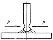
The strength of the electromagnetic zero lies in the fact that the electric current, passing through the electrode, forms a magnetic force field around it, which exerts a compressive effect on the surface of the electrode, tending to reduce the cross-section of the electrode. The magnetic force field does not affect solid metal. Magnetic forces acting normally to the surface of a spherical molten drop have a significant effect on it. With an increase in the amount of molten metal at the end of the electrode under the action of surface tension forces, as well as compressive magnetic forces, an isthmus forms in the area between the molten and solid electrode metal (Fig. 39). As the cross-section of the isthmus decreases, the current density sharply increases and the compressive effect of magnetic forces, tending to detach the drop from the electrode, increases. The magnetic forces have a minimal compressive effect on the spherical surface of the droplet facing the molten bath. This is due to the fact that the current density in this part of the arc and on the product is small, therefore, the compressive effect of the magnetic force field is also small. As a result, the metal is always transferred in the direction from the small electrode (rod) to the large electrode (product). It should be noted that in the formed isthmus, due to an increase in resistance during the passage of current, a large amount of heat is released, leading to strong heating and boiling of the isthmus. The metal vapors formed during this overheating at the moment of detachment of the drop have a reactive effect on it - they accelerate its transition to the bath. Electromagnetic forces promote metal transfer in all spatial welding positions.
The force of internal gas pressure arises as a result of chemical reactions, which proceed more actively, the more the molten metal at the end of the electrode is overheated. The initial products for the formation of reactions are gases, and the volume of the gases formed is tens of times greater than the volume of the compounds involved in the reaction. The separation of large and small drops from the end of the electrode occurs as a result of violent boiling and removal of the formed gases from the molten metal. The formation of splashes on the base metal is also explained by the explosive fragmentation of the drop when the drop passes through the arc gap, since at this moment the release of gases from it increases, and some part of the drop flies out of the weld pool. The force of the internal pressure of the gases mainly moves the droplet from the electrode to the workpiece.
Main indicators of the arc welding process
Melting ratio... When welding metal, the seam is formed due to melting of the filler and penetration of the base metal.
Filler metal melting is characterized by a melting coefficient
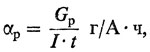
where α p is the melting coefficient; G p is the mass of the electrode metal melted over time t, g; t is the arc burning time, h; I - welding current, A.
The melting coefficient depends on the composition of the wire and electrode coating, the weight of the coating, as well as the type and polarity of the current.
Loss factor... The coefficient characterizes the loss of the metal of the electrode for spattering, evaporation and oxidation.
where ψ is the loss factor; G H - mass of deposited metal, g; G p is the mass of molten metal, g.
The loss factor depends not only on the composition of the wire and its coating, but also on the welding mode and type welded joint... The loss factor increases with increasing current density and arc length. It is slightly less when welding in Tavr, with cutting of crowns, than when surfacing.
Deposition coefficient... To assess the surfacing process, the concept of surfacing coefficient is introduced:
![]()
where α H is the deposition coefficient; G H - mass of the metal deposited over time t, g (taking into account losses).
The deposition coefficient depends on the type and polarity of the current, the type of coating and the composition of the wire, as well as on the spatial position in which welding is performed.
Dependence of the value of the welding current on the diameter of the electrode... In manual arc welding, the welding current and the diameter of the electrode are related by the following relationship I = K × d, where I is the value of the welding current, A; K - coefficient depending on the brand of the electrode (K = 40 ÷ 60; 40 - for alloyed electrodes; 60 - for carbon ones); d - electrode diameter, mm.
The above formula is applicable for electrodes with a diameter of 3 - 6 mm.
The relationship between the diameter and the value of the welding current is also expressed by the following experimental formula I = (m + n - d) - d, where m = 20; n = 6 (for manual welding with steel electrodes).
Arc welding process productivity... Welding productivity is determined by the amount of deposited metal G = α H × I × t where G is the mass of the deposited metal, g.
The higher the current, the higher the performance. However, with a significant increase in the welding current for the applied diameter of the electrode, the latter can quickly be heated by the heat of Lenz-Joule, which will drastically reduce the quality weld, since the weld metal and the fusion zone of the base metal will be overheated. It should be noted that overheating of the electrode will increase metal spatter.
Heat input... The ratio of the effective thermal power of the arc (source) q and to the speed of movement of the arc ν is called heat input.
![]()
where ν is the arc movement speed (welding speed), cm / s.
Heat input is the amount of heat in calories injected per unit length of a single pass seam or bead.
The total thermal power of the welding arc is approximately considered equal to the thermal equivalent of its electrical power Q = 0.24 U d × I, cal / s, where U d is the voltage drop across the arc, V; I is the value of the welding current, A; Q is the thermal equivalent of the electric power of the welding arc, cal / s.
The amount of heat introduced by the welding arc into the product during its heating per unit of time is called effective thermal power of the welding arc, which is the sum of thermal energy released in the arc spot on the item, introduced into the item during heat exchange with the arc column and spot on the item and supplied with drops of molten flux, electrode metal and coating q u = - 0.24U d × I × h and cal / s, where q and is the effective thermal power of the welding arc, cal / s; h and is the effective efficiency of the metal heating process by the welding arc.

Effective to. And. e. the process of heating metal with a welding arc called the ratio of the amount of heat introduced into the metal to the thermal equivalent of the electric power of the arc. This coefficient characterizes the efficiency of the processes of heat release and heat transfer in the arc gap in relation to the heating of the metal of the product and depends mainly on the welding method.
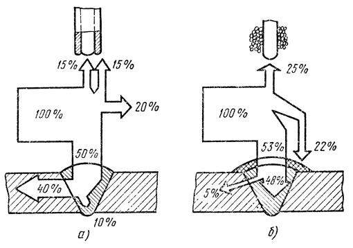
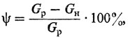
In fig. 40 shows the heat balance of the heat released by the arc, from which it can be seen that the heat of the arc is more fully used in automatic submerged arc welding. With an increase in the length of the arc, the effective efficiency decreases and increases with the deepening of the arc into the bath. When welding with metal electrodes, this coefficient depends little on the type, polarity and magnitude of the welding current.
Self-test questions
- What is called an electric arc?
- What are the main areas of the electric arc?
- What phenomena result in ionization of the air gap between the electrode and the product?
- How to determine the coefficients of melting, deposition and loss?
- What is called the running energy?
The arc voltage, that is, the voltage between the electrode and the metal to be welded, depends mainly on its length. The shorter the arc, the lower the voltage, although the current in the arc may remain constant. This is due to the fact that with a long arc, the resistance of the gas gap will be greater. As is known from electrical engineering, the higher the resistance, the higher the voltage must be in order to ensure the passage of the same current in the circuit. The total voltage drop in the arc (Ua) is the sum of the voltage drop in the cathode zone (£ / k), in the arc column (UCT) and in the anode zone (t / a), i.e.
The absolute value of the arc voltage can also be influenced by the composition of the electrode and the metal being welded, the composition and pressure of the gaseous medium surrounding the arc (air, argon, helium, carbon dioxide) and other factors.
The arc when welding with a metal electrode burns steadily at a voltage of 18-28 V, and when welding with a carbon or graphite electrode, at a voltage of 30-35 V. To strike the arc, a higher voltage is required than is necessary to maintain its normal burning. This is due to the fact that at the initial moment the air gap is not yet sufficiently heated and it is necessary to give the electrons a high speed to ionize the atoms of the gas gap, which can be achieved only at a higher voltage at the moment of arc ignition.
In fig. 22 shows graphs of changes in voltage and current in the arc during its ignition and stable burning. The curve showing the relationship between voltage and current in the arc is called the static (or volt-ampere) characteristic of the arc and corresponds to the steady-state (stationary) arc burning. Point A marks the moment the arc is struck. The arc voltage then rapidly drops to a normal value corresponding to a steady arc. A further increase in the current increases the heating of the electrode and the rate of its melting, but does not affect the stability of the arc burning.
The arc has a falling static characteristic at a relatively low current density used in manual arc welding or in automatic submerged arc welding at medium modes. At higher current densities (submerged arc welding at high current, welding with a small-diameter wire in a shielding gas), the static characteristic of the arc will increase, as is conventionally shown in Fig. 22 with dotted lines 3 and 4.
An arc is called stable, burning evenly, without arbitrary breaks that require re-ignition. If the arc burns unevenly, often breaks off and goes out, then such an arc is called unstable. The stability of the arc depends on many reasons, the main of which are the type of current, the composition of the coating of the electrodes, the polarity and length of the arc.
The arc length is equal to the distance between the end of the electrode and the surface of the molten metal of the welded product. Typically, the normal arc length should not exceed 3-4 mm for the rest of the electrode. Such an arc is called short. The short arc burns steadily and ensures the normal course of the welding process. For electrodes with a diameter of 4-5 mm with an OMM-5 coating, the normal arc length is 5-6 mm. An arc with a length greater than 6 mm is called long. The process of melting the metal of the electrode with such an arc is uneven. In this case, metal droplets flowing down from the end of the electrode can be oxidized to a greater extent with oxygen and enriched with nitrogen in the air. The weld metal is porous, the weld has an uneven surface, and the arc is unstable. With a long arc, productivity decreases, metal spattering increases, places with lack of penetration and insufficient fusion of the deposited metal with the base metal are more often formed.
arc_ can be powered from a direct or "alternating current" source. The arc can be powered by direct current of direct and "reverse" polarity. "With direct polarity, the minus of the current source is connected to the electrode, and with reverse polarity, to the workpiece to be welded. When welding with a carbon electrode, the arc is easier to start and burns more steadily if the current is of direct polarity. Reverse polarity current is used in cases where it is necessary to reduce the generation of heat on the welded product: when welding thin or low-melting metal, sensitive to overheating of alloyed, stainless and high-carbon steels, etc., as well as when using some types of electrodes (for example, with coating UONI-13).
To determine the polarity of the DC circuit, dissolve half a teaspoon of table salt in a glass of water, lower both circuit wires into the solution and turn on the welding current. The wire, near which there is an intensive evolution of gas (hydrogen) bubbles, will be negative, and the second - positive. The ends of the wires at a length of 1-2 cm must be stripped of insulation. To determine the polarity of the current, special pole indicators are also used.
In fig. 23 shows the curves of voltage and current changes in an alternating current arc for one period. Since in each half-period the current (1d) and arc voltage ((/ j change from zero to maximum values), the temperature of the arc column and the degree of ionization of the arc gap decrease over the same period of time. an increased voltage is required equal to U3ax, which is greater normal voltage arcs UR.
To increase the stability of the AC arc burning, elements with a low ionization potential are introduced into the electrode coatings and into the welding fluxes: potassium, sodium and calcium, which facilitate the initiation of the arc after the current decreases to zero, and at the same time changes its direction to the opposite.
Magnetic fields are generated around the arc and in the metal being welded. If these fields are asymmetrically located relative to the arc axis, then they can deflect the arc, which is a flexible current conductor, which makes welding difficult. The deflecting effect of magnetic fields on the welding arc is called magnetic blast.
The strength of the magnetic field is proportional to the square of the current; therefore, magnetic blast is especially noticeable when welding with direct current of a significant value (over 300-400 A). When welding with alternating current with thick-coated electrodes and submerged arc welding, the phenomenon of magnetic blowing is much weaker than with direct current and when using bare or thin-coated electrodes.
The magnitude of the magnetic blast is also influenced by the location of the iron (ferromagnetic) masses near the welding site, the place where the current is supplied to the product, the shape of the product, the type of welded joint, the presence of gaps and other reasons. To reduce the deflecting effect of magnetic fields on the arc, welding should be carried out with the shortest possible arc, the welding current should be supplied to the product at a point located as close as possible to the place of the arc, and the angle of inclination of the electrode should be changed so that the lower end of the electrode is turned to the side action of magnetic blast.
In fig. 24 shows how the influence of the place of supply of current to the product affects the deflection of the arc.
To reduce the influence of large ferromagnetic masses, a massive steel plate is laid on the welded product on the side opposite to the arc deflection direction. One wire from the source is connected to a steel plate, which is laid at a distance of 200-250 mm from the welding place, gradually moving it along the seam as it moves arcs.